Hearing Aid Circuit using 1.5V Battery is small sound booster, which helps people with hearing loss and to hear better.
Furthermore, it picks the weak sound and makes it louder in earphone, also this circuit works with one 1.5V battery.
Circuit Working:
Parts List:
| Components | Values | Quantity |
|---|---|---|
| Resistors (All resistors are 1/4 watt unless specified) | 10k | 2 |
| 220k | 1 | |
| 330k | 1 | |
| 3.3Ω | 1 | |
| Capacitors | Ceramic 22nF | 1 |
| Electrolytic 10µF 25V | 1 | |
| Semiconductors | Transistor BC547 | 2 |
| Transistor BC557 | 1 | |
| Electret Mic | 1 | |
| Earphone 8Ω | 1 | |
| ON/OFF Switch | 1 | |
| Battery 1.5V | 1 |
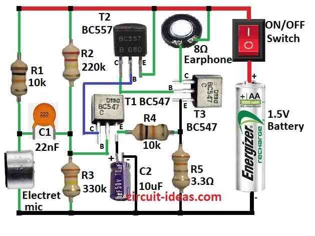
Above is a simple hearing aid circuit diagram and below is how it works:
Mic picks sound and turns it into small signal and transistor T1 BC547 makes weak signal stronger.
Also, resistor R3 330k and capacitor C2 10uF control how much T1 amplifies and capacitor C1 22nF blocks DC from going to T1 base, then resistor R1 10k limits current to T1 base.
Moreover, transistor T2 BC557 gives more amplification and then resistor R4 10k sets T2 bias point.
After that, transistor T3 BC547 works as output amp which makes signal strong for earphone and resistor R5 3.3 ohm controls current to T3 base.
10k resistor and 10uF capacitor does two jobs, first keep stable bias for all transistors and second make simple AGC (automatic gain control).
AGC works like this:
Loud sound makes more voltage on R3, C2 passes it to T1 base, T1 gain goes down and avoids sound distortion.
Formula:
Preamplifier circuit for hearing aid uses electret mic and 1.5V battery, also it must use low power and give enough gain to boost weak mic signal.
Gain (Av) of Preamplifier:
Gain tells how much the mic signal is amplified and for simple transistor amplifier for common emitter the formula is:
Av = –RC / re
- RC is collector resistor.
- re is internal emitter resistance of transistor.
For better results ,we can improve the gain, frequency and power consumption and perform more precise calculations based on your requirements.
How to Build:
To build a Hearing Aid Circuit using 1.5V Battery follow below connection steps:
Circuit Connection:
- First, positive terminal goes to 1.5V battery and then negative terminal connects to ground.
- Next, mic positive side connects to one end and other end goes to collector of T3.
- Then T1 base connects to two resistors R2, R3 between (+) and ground, T1 collector goes to base of T2 and T1 emitter connects to ground through capacitor C2.
- After that, resistor R1 connects from (+) to mic and ground.
- Now T2 base connects to T1 collector, emitter to (+) and collector to base of T3.
- Also, resistor R4 goes between emitter of T1 and T3.
- Then T3 emitter goes to ground through resistor R5, T3 base connects to T2 collector and collector goes to (+) through earphone.
- Finally, ON/OFF switch connects to (+) side of 1.5V battery.
Note:
- This is very simple circuit and is not good for people with strong hearing loss, so use correct components and build on PCB properly.
- Also, wear ESD protection when making circuit.
Conclusion:
To conclude, Hearing Aid Circuit using 1.5V Battery gives low power sound boost; also it is good for learning but has limits.
As a result, it is not for all hearing needs but it is better to ask hearing doctor for right hearing aid.