A High Power Three Phase Bridge Rectifier Circuit is super important in factories and places where we need a lot of DC voltage and current.
It changes three phase AC voltage into a steady DC output, which is really important for running motors, power supplies and other things.
The IC 20L6P45 is like the three phase diode bridge rectifier, but it has some cool benefits!
It takes up less space, is lighter, is simpler and works really efficiently with high voltage and current ratings.
This circuit also needs a good heat sink to soak up extra heat.
This article will discuss about how it works, how it is built and the calculations behind a three phase full wave rectifier using the 20L6P45 module.
Circuit Working:
Parts List:
| Component Type | Specification | Quantity |
|---|---|---|
| Capacitors | Electrolytic 470µF 450V | 4 |
| Semiconductors | IC 20L6P45 | 1 |
| Inductor Coils | 100mH / 15 SWG | 2 |
In this article the circuit is made to change three phase alternating current AC into direct current DC using a special part chip called the 20L6P45 which is three phase full wave rectifier module.
It takes power from three different phases which are Phase A, Phase B and Phase C and turns them into a bumpy kind of DC voltage.
To make the DC voltage smoother and more stable we use some capacitor filters called C1, C2, C3 and C4.
These capacitors help by charging up and letting go of energy when needed which keeps the DC voltage steady.
We have used inductors coils L1 and L2 to the circuit to improve the output quality and reduce any ripples making the current flow more even.
The IC 20L6P45 rectifier module acts like a three-phase diode bridge allowing current to move in just one direction.
This is super important for changing the alternating current into direct current effectively.
Formulas with Calculations:
Below are the formulas with calculations for better understanding for Simple High Power Three Phase Bridge Rectifier Circuit:
DC Output Voltage Vdc:
= (3 × Vrms) / π
Vrms is the RMS value of phase voltage
For, a 440V system the phase voltage Vrms:
= 440V / √3 = 254V
So, Vdc = (3 × 254) / π = 243V
Ripple Frequency:
For a three phase rectifier the ripple frequency is six times the AC supply frequency
fripple = 6 × fsupply
For a 50Hz AC supply fripple = 6 × 50 = 300Hz
Capacitor Selection:
The capacitor value is chosen based on load current and ripple voltage
C = Iload / (fripple × Vripple)
Inductor Selection:
The inductor value is selected to maintain continuous current flow and reduce ripple
L = (Vdc × D) / (ΔI × f)
- D is duty cycle
- ΔI is current ripple
- f is switching frequency
How to Build:
To build a Simple High Power Three Phase Bridge Rectifier Circuit follow the steps mentioned below for connections and assembling:
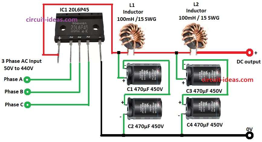
- Gather all the components as mentioned in the above circuit diagram:
- Connect pin 1 of IC1 to the junction of capacitor C1 positive and one terminal of inductor coil L1.
- Connect pin 2 of IC1 to AC Input of Phase A
- Connect pin 3 of IC1 to AC Input of Phase B
- Connect pin 4 of IC1 to AC Input of Phase C
- Connect pin 5 of IC1 to GND of the circuit.
- Connect inductor coil L1 between positive of capacitors C1 and C3 and negative of capacitor C1 and C3 connect to positive of capacitor C2 and C4
- Connect the negative of capacitor C2 and C4 to GND of the circuit.
- Connect inductor coil L2 between positive of capacitor C3 and DC output and negative of DC output connect to GND.
Conclusion:
This Simple High Power Three Phase Bridge Rectifier Circuit, which uses the 20L6P45 module does a great job of changing AC power into a steady DC voltage.
By using capacitor filtering and inductor smoothing, it provides a nice clean DC output that works well for things like motor drives and power supplies in factories.
Choosing the right parts is really important to make sure everything works well and to keep the output voltage nice and smooth.
References:
3 Single Phase Full Bridge Rectifiers for 3 Phase Rectification
Leave a Reply