Metal Detector Circuit using IC CS209A is a cool tool to find metal near by.
It is used for security, treasure hunt and in industries.
This article shows simple but strong circuit using one chip called CS209A.
It is easy to make and works great to detect metal.
We can find metal from few inches away.
The circuit runs on 9V battery which is easy and useful for all.
Circuit Working:
Parts List:
| Component Type | Specification | Quantity |
|---|---|---|
| Resistors (All resistors are 1/4 watt unless specified) | 10k | 1 |
| 220Ω | 1 | |
| 1k | 1 | |
| Potentiometer 10k | 1 | |
| Capacitors | Ceramic 2.2nF | 2 |
| Electrolytic 10µF 25V | 1 | |
| Semiconductors | IC CS209A | 1 |
| LED any 5mm, 20mA | 1 | |
| Coil Inductor 100µH | 1 | |
| Piezo Buzzer | 1 | |
| ON/OFF Switch | 1 | |
| 9V Battery | 1 |
LC circuit with L1 and C1 makes fixed frequency.
Metal near L1 changes inductance and frequency shifts.
CS209A chip sees this change and turns ON the output.
LED1 lights, piezo buzzer makes sound when metal is found.
When metal goes away frequency is normal again with LED1 and buzzer OFF.
VR1 potentiometer changes circuit sensitivity.
Formulas with Calculations:
Formulas and calculations help to make simple metal detector using CS209A.
LC Frequency Formula:
f = 1 / (2 * π * √(L * C))
where,
- L is the 100µH
- C is the 2.2nF
Add values:
f = 1 / (2 * 3.1416 * √(100 * 10⁻⁶ * 2.2 * 10⁻⁹))
f = 339 kHz
So circuit runs at about 339 kHz with no metal.
When metal comes near the frequency changes and detector gets triggered.
How to Build:
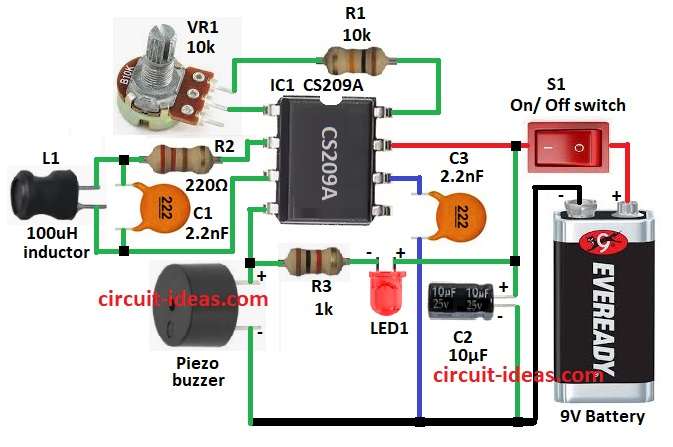
To build a Metal Detector Circuit using IC CS209A follow the below mentioned steps for connections of circuit:
- Collect all parts shown in circuit diagram.
- Pin 1 of CS209A go to one side of VR1 and other side of VR1 go to R1 and then R1 go to pin 8 of IC.
- Pin 2 go to one side of L1 through R2 and other side of L1 go to pin 3.
- C1 connect between R2 and L1.
- Pin 4 go to one side of piezo buzzer and other side of buzzer go to GND.
- Pin 6 go to GND with capacitor C3.
- Pin 7 go to +9V battery through S1 switch and also connect C2 the positive to pin 7 and negative to GND.
- R3 and LED1 connects in series between pin 4 and buzzer and other end go to pin 7 and positive of C2.
Conclusion:
This Metal Detector Circuit using IC CS209A is easy to build, works well and is good for beginners.
IC CS209A makes circuit small and strong for finding metal.
If required change L and C values to set sensitivity for different needs.
Leave a Reply