This Simple Pulse Position Modulation Circuit using IC 555 uses one special chip with number 555.
It works like messenger for your electronic things.
It send info by making small burst like electric pulse.
Not like Morse code with dot and dash but this one uses timing change of pulse to talk.
Pulse strength and size doe not change but remains always the same.
But gap between each pulse become small or big as it depend what message it gives.
Like this circuit can tell many thing just by small time jump.
Circuit Working:
Parts List:
| Category | Component | Quantity |
|---|---|---|
| Resistors | 4.7k 1/4 watt | 1 |
| 10k 1/4 watt | 1 | |
| Capacitors | Ceramic 1nF | 1 |
| Electrolytic 10µF 25V | 1 | |
| Semiconductors | IC 555 | 1 |
In PPM full name Pulse Position Modulation pulse size amplitude)and pulse width stay the same but pulse position changes.
It can change because of the modulating signal value.
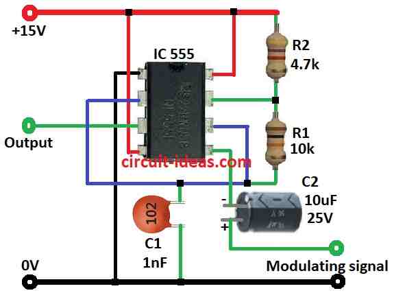
Circuit diagram above show easy PPM circuit using IC 555.
In this circuit each pulse move position width and timing period of pulse can also change when modulating signal change.
When we give modulating signal to pin 5 the control voltage pin and the top voltage level called UTP becomes 2Vcc/3 + Vmod.
If Vmod goes high UTP also goes high and pulse become wider.
If Vmod go low then UTP also goes low and pulse become smaller.
So pulse width is not same it keep changing.
We can find pulse width W using formula given below.
Also we can find period T with another formula shown later.
Gap between pulses are always same as it is 0.693 × R2 × C.
This type of circuit is used in many places like sending voice or data in communication systems.
Formulas and Calculations:
Because 555 IC is easy to use and flexible then people use it many time to make PPM pulses.
In this design 555 IC work in monostable mode and it makes one pulse with fixed size width W when triggered.
We can use this formula to find pulse width W in PPM circuit using 555 IC:
W = – (R1 + R2) × Cin × [ (Vcc – UTP) / (Vcc – 0.5 × UTP) ]
where:
- W is the pulse width in seconds
- R1, R2 is the resistors connect to pin 5 of control voltage
- Cin is the capacitor at pin 2 trigger pin
- Vcc is the supply voltage
- UTP is the upper threshold voltage which is around 2/3 of Vcc
How formula work:
This formula tell us how much time capacitor Cin take to charge from trigger voltage to UTP.
The time it takes to charge is how wide the pulse will be.
Part (R1 + R2) × Cin show RC time constant the charging time
Part (Vcc – UTP) / (Vcc – 0.5UTP) fix special behavior of 555 IC.
Key Points:
Total period T = pulse width + gap time
Gap between pulses depends on R2 and capacitor
This formula help know how parts control pulse timing in PPM system.
How to Build:
To build a Simple Pulse Position Modulation Circuit using IC 555 follow the below mentioned steps:
- Connect pin 4 and pin 8 Vcc of 555 IC to positive side of power.
- Take modulating signal Vmod and give it to control voltage pin 5 which uses one capacitor C2 10µF in between.
- Join resistor R1 10k and R2 4.7k in series and connect them between pin 7 and threshold pin 6.
- Put one capacitor C1 1nF from pin 2 to ground.
- Pin 3 is output which takes signal from there.
- Be sure pin 2 trigger is also connected to pin 6 threshold.
- Pin 1 connects to ground and connect it to negative side of power.
Note:
- We can change values of R1, R2 and capacitor Cin to get different pulse width or signal style.
- Use good power supply and right signal level.
- Wrong one can break the IC or whole circuit.
Conclusion:
A Simple Pulse Position Modulation Circuit using IC 555 is easy and useful way to make pulses where each pulse move place based on input signal.
PPM is good because it fight noise better and uses bandwidth in smart way that is why it is used in communication and other systems where timing and signal need to be correct.
In this circuit 555 IC work in monostable mode is main part that make PPM pulse and it is strong and flexible for this job.