QRP is word in ham radio which means to send signal with low power.
It come from Morse code.
‘QRP’ say “lower your power” and this QRP use power rules like:
Simple QRP Antenna Tuner Circuit for RF Applications help send signal better.
It connect low power radio to antenna.
Tuner fix mismatch, stop power loss and send power good.
It is very useful when using under 10 watts.
Tuner has coil (inductor), some capacitors and switch to change capacitor value.
This help to match different antennas with good work.
Circuit Working:
Parts List:
| Component Type | Specifications | Quantity |
|---|---|---|
| Capacitors | Ceramic 300pF, 270pF, 510pF | 1 each |
| Semiconductors | SPDT Switch | 1 |
| Inductor 50µH | 1 | |
| BNC sockets coaxial cable connector | 1 |
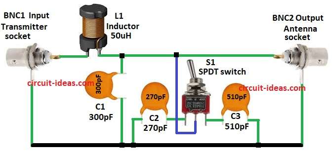
One coil L1 and three capacitors like C1, C2, C3 make LC circuit and it help match transmitter to antenna.
Switch S1 SPDT lets user pick capacitor value of 270pF or 510pF.
This change how circuit works.
Changing capacitors help match impedance and keep SWR low.
Low SWR means better power goes from radio to antenna.
SWR meter can check power going out.
This circuit is made for QRP means low power.
It is good for ham radio people using small power.
Formulas with Calculations:
Below are formulas and math for simple QRP antenna tuner for RF use:
Resonant Frequency Formula:
f = 1 / (2 * π * √(L * C))
where:
- f is the frequency in Hz
- L is the inductance in H
- C is the capacitance in F
Resonant Frequency Calculations:
L = 50µH and C = 300pF
f = 1 / (2 * 3.1416 * √(50×10⁻⁶ * 300×10⁻¹²))
f = 6.57 MHz
L = 50µH and C = 270pF
f = 6.88 MHz
L = 50µH and C = 510pF
f = 5.45 MHz
These formulas help find what frequency the LC circuit works best at and is useful to tune antenna for QRP at low power radio.
How to Build:
To build a Simple QRP Antenna Tuner Circuit for RF Applications following steps are required to follow:
- Connect BNC1 to one side of L1 inductor and other side of L1 goes to C1 and GND.
- Connect S1 switch between C1 and BNC2.
- First pin of S1 goes to C2 and GND.
- Second pin of S1 connects to line between L1 and BNC2.
- Third pin of S1 goes to C3 and GND.
Conclusion:
This Simple QRP Antenna Tuner Circuit for RF Applications is easy and useful for low power RF use.
It helps ham radio users match impedance, lower SWR and send signal better.
By picking right capacitor user can tune for different frequencies.
It is good for QRP and ham radio work.
Leave a Reply