A Simple SCR Based Low Battery Display Circuit helps us know when the 9V battery voltage drops near the critical level.
For example, if the 9V battery level reaches 8.3V or 8.6V then the LED glows and because of this, the user can replace the battery before the connected device stops working.
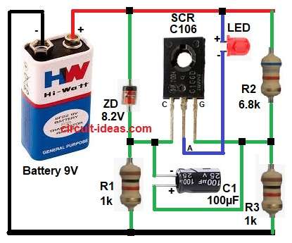
This circuit uses a Zener diode, one SCR C106, one LED, resistors and one capacitor, the design is simple, low cost and easy to build on a general PCB board.
Also, the SCR gives a latching action and therefore, once triggered the LED indication becomes stable.
Circuit Working:
Parts List:
| Components | Values | Quantity |
|---|---|---|
| Resistors | 1k 1/4 watt | 2 |
| 6.8k 1/4 watt | 1 | |
| Capacitor | Electrolytic 100µF 25V | 1 |
| SCR C106 | 1 | |
| Any standard LED | 1 | |
| Zener Diode 8.2V | 1 | |
| Battery 9V | 1 |
First, battery voltage stays good and near 9V and Zener diode ZD checks the voltage level.
As long as voltage stays above Zener limit, the SCR gate does not get enough trigger current and so LED stays OFF.
However, when battery voltage starts dropping then voltage around Zener and SCR gate line changes.
Then Zener diode and resistor network send small trigger current to SCR gate.
As soon as SCR gets gate current then it turns ON.
Next, current flows through LED and resistor R2, so LED starts glowing and this glowing LED shows battery voltage is low.
After that, SCR keeps LED ON because of latching action and hence indication stays visible until battery disconnects.
Also, capacitor C1 helps stop false triggering from sudden voltage changes and noise.
Formulas with Calculations:
Low battery trigger voltage formula:
The approximate trigger voltage depends on Zener voltage and SCR gate trigger voltage.
Vtrigger = Vz + VGT
where,
- Vtrigger is voltage level where circuit starts working
- Vz is Zener diode voltage
- VGT is SCR gate trigger voltage
Like if we take:
Vz = 8.2V
VGT = 0.1V to 0.2V effective difference in this network or around 0.4V which is typical maximum
Then:
Vtrigger = 8.2 + 0.1
Vtrigger = 8.3V
or
Vtrigger = 8.2 + 0.4
Vtrigger = 8.6V
Note: Because of resistor network action, capacitor charge, SCR sensitivity and Zener tolerance, the LED may start glowing anywhere between 8.3V and 8.6V.
How to Build:
To build a Simple SCR Based Low Battery Display Circuit following steps are needed for connections:
- Start, the circuit by first collecting all circuit parts.
- Next, take the battery and connect battery positive terminal to positive rail.
- Then connect battery negative terminal to ground rail.
- After that, take Zener diode ZD and connect Zener cathode to positive rail.
- Then connect zener anode to center junction where resistor R1 and SCR gate line connect.
- Next, take SCR C106 and connect anode to LED cathode side.
- Then connect cathode to junction of Zener diode, resistor R1 and capacitor C1 negative terminal.
- Finally, connect gate to junction of resistor network R2, R3 and capacitor C1 positive terminal.
Conclusion:
This Simple SCR Based Low Battery Display Circuit is easy and reliable, as it gives clear LED warning when battery voltage goes low.
Also, SCR latching keeps indication stable, so this circuit works well for battery operated projects and small portable devices.
Leave a Reply