This Solar Motor Robot Circuit run by sun with no battery needed.
It uses special circuit called “solar engine” which works good with small solar panel.
Robot can move even when sky is cloudy.
Circuit Working:
Parts List:
| Category | Component | Quantity |
|---|---|---|
| Resistors (All resistors are 1/4 watt unless specified) | 100k | 1 |
| 1M | 1 | |
| 10k | 1 | |
| 390Ω | 1 | |
| 470k | 3 | |
| Capacitors | Ceramic 47nF | 1 |
| Electrolytic 4700µF 25V | 1 | |
| Semiconductors | Transistor BC547 | 2 |
| Transistor BC557 | 1 | |
| Transistor 2N2905 | 1 | |
| LED Green 5mm, 20mA | 1 | |
| DC Motor 3V | 1 | |
| Solar Panel 3V | 1 |
This simple circuit like tiny solar power plant for robot.
It take light and stores energy and then release in small bursts to run motor, coil or other parts.
Solar engine can release power based on voltage, time or how fast energy come in.
People call it “relaxation oscillator” which is like robots energy heart.
Think like small energy bank which saves little power from solar panel and then uses it for short action.
Robot can work even with low sunlight.
This version is smarter and it uses 2 transistors to keep power ON until voltage drop to 1.5V.
Old one stop at 2.8V so this new design gives motor more energy from capacitor.
More power means more push!
Formulas:
Making a relaxation oscillator solar engine means building a circuit that charge a capacitor with sun power which then releases it to make pulses means oscillations.
Formula for timing (T):
T = 0.693 × R × C
- T is the time in seconds
- R is the resistor in ohms
- C is the capacitor in farads
To get good result for our robot or project we need to test and adjust based on use and weather.
How to Build:
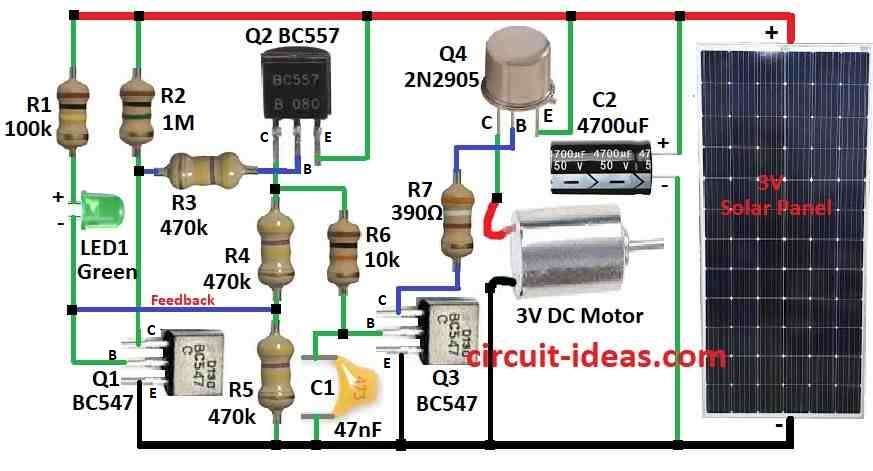
To build a Solar Motor Robot Circuit we need to follow the below mentioned connections steps:
- Connect Q1 collector to positive (+) through resistor R2.
- Connect Q1 base to positive (+) through R1 and LED1.
- Connect Q1 emitter to ground (-).
- Connect Q2 collector to ground (-) through R4 + R5 in series.
- Connect Q2 base through R3 resistor.
- Connect Q2 emitter to positive (+).
- Connect Q3 collector to Q4 base through R7.
- Connect Q3 base to ground (-) through C1 capacitor.
- Connect Q3 emitter to ground (-).
- Connect Q4 collector to 3V motor one leg.
- Connect Q4 base to Q3 collector.
- Connect Q4 emitter to positive (+).
- Connect C2 capacitor between positive (+) and ground (-).
- Connect 3V solar panel to positive (+) and ground (-) of power.
Note:
- Follow the circuit diagram carefully and double check all wires are properly connected before putting the power ON.
Conclusion:
This Solar Motor Robot Circuit is good for beginners and is simple design with few parts.
It work even in weak sunlight and is great for learning or fun solar bots!
Leave a Reply