Squelch circuits are like the radio peace assistant!
This small smart circuit stops radio sound when no strong signal connects.
So no more hearing of bad noises but only when signal is strong one can hear good sound or video.
Best thing about squelch is its very easy and works with many radio types.
It keeps radio quiet when there is no need of sound and let the fun things happens when signal is good.
Circuit Working:
Parts List:
| Component | Quantity |
|---|---|
| Resistors (All resistors are 1/4 watt) | |
| 10k | 2 |
| 68k | 4 |
| 2.2k | 3 |
| 100k | 1 |
| Potentiometer 1M | 1 |
| Capacitors | |
| Ceramic 100nF | 2 |
| Ceramic 150nF | 1 |
| Electrolytic 10µF 16V | 1 |
| Semiconductors | |
| IC (A1, A2 = IC1) TLC272 | 1 |
| Transistor BC547 | 1 |
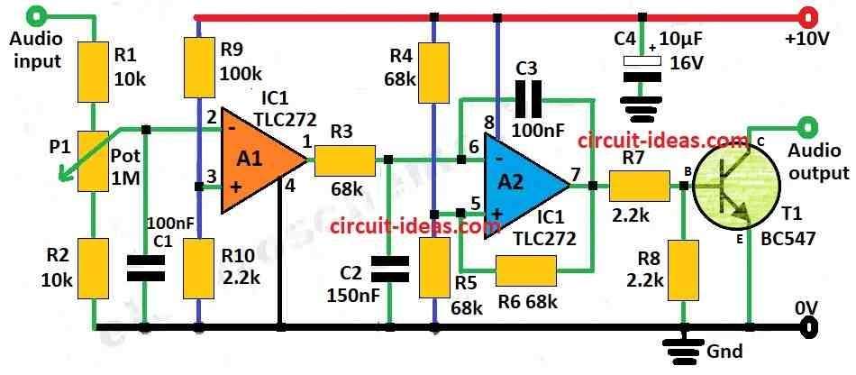
Signal come from receivers RAA circuit which then goes through R1, R2 and P1 part which changes a bit.
From P1 a signal goes to input of op-amp A1 which work like comparator.
We give 200 millivolt to A1s non-invert input and using resistor R9 and R10 to make that voltage.
A1 send output to A2 which is a schmitt trigger but before that it go through filter made with capacitor C2 and resistor R2.
This filter is very important as it stop small noise signals from messing up squelch working.
Capacitor C3 help to make signal from A2 more smooth and this make the sound control feel better and not rough.
After that A2 output connects to base of transistor T1 using resistors R7 and R8 like voltage divider.
Squelch output is open collector type we can use it to stop audio signal when needed.
Whole circuit only uses little power which is less than 10 milliamp.
So it easy to use with many radios but only if power supply is okay.
Formula:
Main job of squelch circuit with op amp is to check how strong signal is and compare with set value.
Op Amp Comparator:
Op-amp compare two voltages one is signal which connects to inverting input and other is fixed voltage which connects to non-inverting input.
Formula for Output:
Vo = A * (V(+) – V(-))
here,
- Vo is output voltage
- A is gain of op-amp which is very big in comparator mode
- V(+) is voltage at non-inverting input for reference
- V(-) is voltage at inverting input which is for input signal
Control Threshold:
We can use voltage divider to change reference voltage because it controls how strong signal must be to turn ON squelch.
Optional: Schmitt Trigger:
We can add Schmitt trigger after comparator because it gives hysteresis and helps to avoid quick ON/OFF switching when loud noise come.
It makes squelch works more smoothly.
Stop Activation:
When signal go below set value then comparator output tell switch like transistor or logic gate to mute audio output.
How to Build:
To build a Squelch Circuit following are the steps one needs to follow:
- Gather all parts one needs and check all are working good and not damage
- Plan how the circuit looks.
- Decide where each part connects and how to connect each other.
- We can use given schematic or make ones own from explanation.
- Put op-amps on breadboard or PCB.
- Connect power pins V+ and V− to correct voltage.
- Follow diagram to connect input and output pins right way.
- Put resistors, capacitors and pot in place as shown in schematic.
- Check the values are correct and capacitor and potentiometer needs correct side too.
- Add transistor T1 like shown in diagram and be careful to connect pins to right place and in correct direction.
Power the circuit:
- Connect the power supply and check voltage and polarity is correct.
Test the circuit:
- Before one finishes building then test circuit first.
- Give different signal strengths to input and watch output.
- Check if squelch works proper and mute when no signal passes when its strong.
Finish assembly:
- If all parts are working good then fix all parts in place.
- Clean up loose wires and make it neat.
Optional:
- We can put circuit in box or connect with bigger project if needed.
Note:
- Always check all wire and parts again are proper connected.
- If not working then check again for some wrong wire or wrong part value.
Conclusion:
In the end this Squelch Circuit is useful way to mute audio when no strong signal connects.
It uses op-amps, resistors, capacitors and one transistor which are not too hard to build.
If put it together carefully and test good one can add it easy to many radios by making them work better and more easy to use.