Thermometer Circuit is like a small detective for heat.
It has got special sensor which smells temperature and then show on the screen like digital thermometer.
These circuits come in many shape and size for the use in different way to feel temperature.
But no matter which one all of them will indicate which one is how hot or cold!
Circuit Working:
Parts List:
| Category | Part Description | Quantity |
|---|---|---|
| Resistors (All resistors are 1/4 watt unless specified) | 10k | 2 |
| 2.2k | 2 | |
| 6.8k | 2 | |
| 680Ω | 1 | |
| 1k | 3 | |
| Preset 2.5k | 1 | |
| Preset 1k | 1 | |
| Capacitors | Ceramic 0.1µF | 1 |
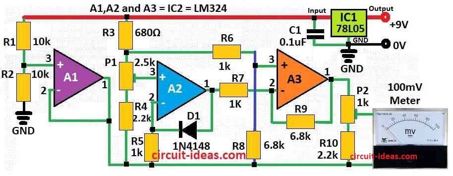
| Semiconductors | IC 78L05 | 1 |
| A1, A2, A3 1C2 = LM324 | 1 | |
| Diode 1N4148 temperature sensor | 1 | |
| 100mV Meter | 1 |
This circuit is a digital thermometer which uses normal 1N4148 diode to feel temperature.
The diode changes voltage when temperature change about minus 2 millivolt for each degree Celsius.
This help measure temperature is good.
To see temperature one should use digital multimeter.
It can show from -9.99°C to +99.9°C.
To set up (calibrate) thermometer do two steps:
Step 1 – Set 0°C:
Put diode in glass with ice and water.
Make sure water is really 0°C and check with normal thermometer.
Now turn P1 until digital meter show 000.
That mean diode feel zero degree.
Step 2 – Set 100°C:
Now put diode in boiling water.
Turn P2 until digital meter show 99.9.
Now it is ready!
Formula:
IC LM324 is a small chip that work like op-amp (operational amplifier).
People use it in many things like thermometer circuits.
In thermometer LM324 uses this easy formula:
Vout = Vref + K*(Vsensor − Vref)
where,
- Vout is output voltage from LM324.
- Vref is fixed voltage for reference.
- Vsensor is voltage from temperature sensor.
- K is gain which shows how much circuit amplify signal.
Vsensor and Vref depend on temperature and how one set up the circuit.
K comes from how one builds the op-amp part with LM324 IC and with resistors and feedback parts.
Note:
This formula show how LM324 help in thermometer job.
But in actual design can change based on what one needs like how much temperature one want to measure and how exact it should be and what kind of screen or display it uses.
How to Build:
To build the Thermometer Circuit follow the below mentioned steps:
How to Build the Circuit:
- Start by putting 1N4148 diode in place.
- Connect it between pin 1 and pin 2 of A2.
- Connect pin 3 of A1 to the point where R1 and R2 meet.
- Join pin 1 and pin 2 of A1 together.
- Connect preset P1 to pin 3 of A2.
- Connect pin 3 of A3 to where R6 and R8 join.
- Use resistor R7 to connect pin 1 of A2 to pin 2 of A3.
- Put resistor R9 between pin 1 and pin 2 of A3.
- Connect pin 1 of A3 to a 100mV meter through preset P2.
- Give power using 9V battery and connect it to circuit using IC1 78L05 regulator.
Note:
- Be sure all wires and parts are connected right and follow the circuit diagram.
- After everything is connected turn ON the power and do calibration (set 0°C and 100°C).
- Now the digital meter should show correct temperature in the range one wants.
Conclusion:
To conclude the Thermometer Circuit is an electronic thing to measure and show temperature.
It got sensor to feel the heat or cold and parts to make signal right and screen or meter to show number.
People use these circuits many places like factories, weather watching, medical tools and home gadgets so they know exact temperature for better control.
What one requires, how near it must be, how hot or cold it must range and what one wants to use it for will decide which sensor to choose and how to construct the circuit.