Walkie Talkie Circuit is small device for talking.
Two people can talk without wire.
It work with radio signal with short distance only.
One person can talk and other can listen but not both at the same time.
This project is good for fun, small chat and learning electronics.
Circuit Working:
Parts List:
| Category | Component | Quantity |
|---|---|---|
| Resistors (All resistors are 1/4 watt unless specified) | 10k | 2 |
| 5.6k | 1 | |
| 22Ω | 1 | |
| 680Ω | 1 | |
| 8.2k | 1 | |
| 3.3k | 1 | |
| Capacitors | ||
| Ceramic 15pF | 1 | |
| Ceramic 1nF | 1 | |
| Ceramic 27pF | 1 | |
| Ceramic 47pF | 1 | |
| Ceramic 100pF | 1 | |
| Ceramic 4.7pF | 1 | |
| Ceramic 47nF | 1 | |
| Ceramic 22nF | 1 | |
| Ceramic 100nF | 1 | |
| Electrolytic 10µF 25V | 1 | |
| Electrolytic 100µF 25V | 2 | |
| Semiconductors | IC LM386 | 1 |
| Transistor BC547 | 1 | |
| Electret Mic | 1 | |
| Antenna Coil As specified | 1 | |
| 22uH Choke | 1 | |
| Antenna | 1 | |
| 8Ω Speaker | 1 | |
| ON/OFF Switch | 1 | |
| Selector Switch | 4 | |
| Battery 6V | 1 |
This is simple walkie talkie circuit.
It uses one IC called LM386 and this IC is small audio amplifier which uses low power.
How it work:
Mic (microphone) catches sound and change to electric signal.
Transistor BC547 and resistors R1, R2, R3 make signal stronger.
Switch changes the mode and talk or listen.
In Talk Transmit Mode:
Switch send signal to coil (antenna).
Coil make electromagnetic wave with signal.
Signal strength depend on current from amplifier.
In Listen Receive Mode:
Switch connect coil to circuit.
Coil catches radio signal from other walkie talkie.
Capacitor C3 help tune signal and remove unwanted noise.
Signal goes to LM386 chip and make sound louder.
Speaker play sound when we can hear.
Switch button control talk or listen:
Press to talk and release to listen.
This circuit is simple and work only at short distance means few meters.
How to Make Antenna Coil:
Coil is very important.
Connect coil to transistor BC547.
Use small slug 3mm wide with 7 to 10mm tall.
Use thin copper wire from 0.3mm to 0.5mm.
Winding Coil:
First make 4 turns on slug and this is the primary coil.
Then wind 2 more turns on top and this is the secondary coil.
After 1 turn of secondary take one wire out (tap) and connect to capacitor C6.
Formulas:
Walkie talkie circuit frequency depend on many things.
Main part is oscillator which make steady carrier signal.
Two common types:
LC oscillator uses coil and capacitor
Crystal oscillator uses crystal for steady signal
Use this formula:
f = 1 / 2π√LC
where:
- L is coil inductance in henry H
- C is capacitor capacitance in farad F
- f is frequency in hertz Hz
This formula can tell how coil and capacitor set the frequency.
Extra Information (Optional):
Some circuit use PLL (Phase Locked Loop) and reference oscillator.
This help get stable and exact frequency.
It work better for many different channels.
So frequency depend on type of oscillator and value of coil and capacitor.
Knowing LC formula help understand how basic frequency is set.
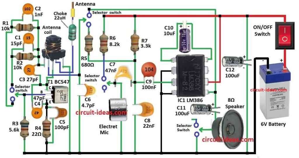
How to Build:
To build a Walkie Talkie Circuit we need to follow the below mentioned components connections steps:
- Connect pin 1 and 5 of IC LM386 with capacitor C10.
- Connect pin 2 and 4 of IC to ground.
- Connect pin 3 of IC with capacitor C9.
- Connect pin 5 also to capacitor C11, 8 ohm speaker and selector switch and then to ground.
- Connect pin 6 to positive power of 6V.
- Connect emitter of T1 BC547 to ground with resistor R4.
- Connect base of transistor to selector switch.
- Connect collector to one side of antenna coil.
- Mic has one side to capacitor C7 and other side to ground.
- ON/OFF switch goes to positive side of 6V battery.
- Antenna coil connects to 22uH choke and antenna.
- One side of antenna coil also connect to capacitors C1, C2, C3 and resistors R1, R2.
Note:
- Be careful while working with electronics.
- We must need some basic electronics and soldering skills.
- Check local laws before using and radio signals which may be regulated.
Conclusion:
This Walkie Talkie Circuit is simple and fun project.
It is good for learning radio and circuit basics.
It is not for long distance or two-way talk at same time.
But it is for short range as it is a good beginner project.