This Whistle Controlled Light Circuit using Arduino is small and fun project, also bulb lights when we whistle.
In this article we have used sound sensor, relay and Arduino Uno and this project is easy and cheap, also the circuit is good for fun, study and small automation.
Arduino Code:
int soundSensor = 8;
int relay = 7;
int statusSensor = 0;

void setup() {
  pinMode(soundSensor, INPUT);
  pinMode(relay, OUTPUT);
  digitalWrite(relay, LOW);
}

void loop() {
  statusSensor = digitalRead(soundSensor);
  if (statusSensor == 1) {
    digitalWrite(relay, HIGH);
    delay(2000);
    digitalWrite(relay, LOW);
  }
}
Coding Explanation:
- We have define pins for sensor and relay.
- Setup function sets input and output.
- Relay starts in OFF state.
- Loop reads sound sensor.
- If whistle detected then sensor gives HIGH.
- Relay turns ON for 2 seconds.
- After 2 seconds relay goes OFF.
- This turns bulb ON and OFF.
Circuit Working:
Parts List:
| Components | Quantity |
|---|---|
| Arduino UNO | 1 |
| Sound Sensor Module | 1 |
| Relay Module | 1 |
| 230V AC LED Bulb | 1 |
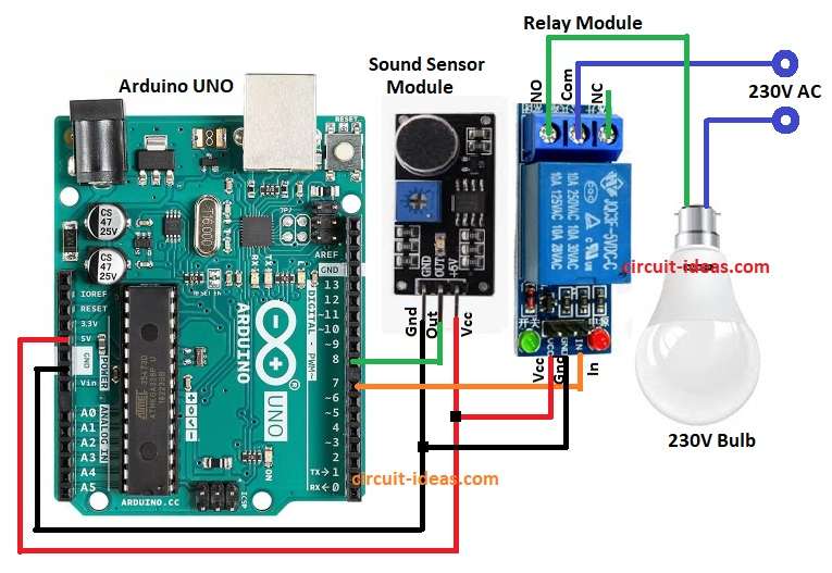
Through the above circuit diagram we will learn to detect whistle using Sound Sensor with Arduino.
Sound sensor and relay get 5V from Arduino and then sound sensor detects loud sound like whistle or clap; it sends HIGH signal to Arduino pin 8.
Then Arduino receives signal and activates pin 7 and pin 7 drives relay module and relay connects AC supply to bulb and finally, bulb glows for 2 seconds then turns OFF.
How to Build:
To build a Whistle Controlled Light Circuit using Arduino follow the below steps for connections:
- First, assemble all the parts as per circuit diagram
- Next, sound sensor VCC(+5V) pin connect to Arduino 5V, sound sensor GND pin connect to Arduino GND and sound sensor OUT pin connect to Arduino digital pin 8.
- After that, connect the relay module VCC pin to Arduino 5V, the relay module GND pin to Arduino GND, and the relay IN pin to Arduino digital pin 7.
- Also, connect the relay COM pin to the phase wire of the AC supply and connect the relay NO pin to one terminal of the 230V bulb.
- Finally, neutral wire connected to other terminal of bulb 230V.
Safety Measures:
- This project uses 230V AC and can cause electric shock or fire.
- Handle with extreme care, only attempt if have experience with high voltage circuits.
- Keep children away.
Conclusion:
Overall, Whistle Controlled Light Circuit using Arduino is whistle control light circuit; Arduino with sound sensor and relay control AC bulb and they work with whistle or clap.
Furthermore, easy to build and is good for beginners and it teaches sensor input, relay use and automation basics.