555 IC Based Schmitt Trigger Circuit is a small project, it work like comparator and comparator is ON/OFF when input cross the voltage; noise make output jump and Schmitt Trigger stop this.
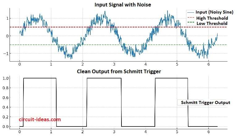
It have 2 limit: high and low. input goes high then output is ON and input goes low then output is OFF.
Moreover, no output change occurs between these two threshold levels and engineers call this behavior hysteresis.
The diagram below shows a noisy sine-wave input at the top and a clean square-wave output at the bottom.
Circuit Working:
Parts List:
| Components | Values | Quantity |
|---|---|---|
| Resistors | 100k 1/4 watt | 2 |
| Capacitors | Ceramic 0.01uF | 2 |
| Semiconductors | IC 555 Timer | 1 |
| Battery 9V | 1 |
First, 555 timer have 2 comparator and it does timing and also Schmitt Trigger work.
Then pin 2 and 6 join together and R1 and R2 give half Vcc bias, then threshold trip is 2/3 Vcc and Trigger trip is 1/3 Vcc.
After that, if C1 is small to 0.001 µF then input pulse get separate and then circuit work like bistable or pulse inverter.
Fast path of C1, R1 and R2 pass only the pulse edge and then this edge set reset and flip-flop output go inverted high.
How to Build:
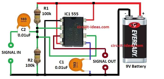
To build a 555 IC Based Schmitt Trigger Circuit follow the below connections steps:
- First, collect all parts as in circuit diagram.
- Next, pin 1 goes to battery negative.
- After that, pin 2 goes between C2 and R1.
- Now pin 3 is square wave which goes at signal OUT and GND.
- Also, pin 4 goes to +9V battery.
- Further, pin 5 goes to C1 0.01µF for stability.
- Then pin 6 connects between R2 and C2 and other side of C2 goes to signal IN and GND.
- Finally, pin 8 connects to battery positive +9V.
Conclusion:
To conclude, this 555 IC Based Schmitt Trigger Circuit is easy and useful, as 555 IC work as Schmitt Trigger and it give stable output even if input is noisy.
This circuit offers a cheap and simple design, and users can apply it in sensors, waveform shaping, and signal conditioning.