The tilt sensor acts like a small switch and changes its state when we tilt or move it; it also detects direction, movement and vibration.
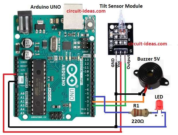
Here we used Arduino Uno with tilt sensor, buzzer and one LED and when sensor tilt, Arduino see it and then Arduino make buzzer ON and LED ON.
Arduino Code:
int tiltPin = 2;
int buzzer = 3;
int led = 4;
int tiltState = 0;

void setup() {
pinMode(tiltPin, INPUT);
pinMode(buzzer, OUTPUT);
pinMode(led, OUTPUT);
}

void loop() {
tiltState = digitalRead(tiltPin);
if (tiltState == HIGH) {
digitalWrite(buzzer, HIGH);
digitalWrite(led, HIGH);
} else {
digitalWrite(buzzer, LOW);
digitalWrite(led, LOW);
}
}
Coding Explanation:
- Tilt sensor pin connected to digital pin 2.
- Buzzer to pin 3 and LED to pin 4.
- Setup define input output pins.
- Loop read sensor value.
- If sensor state is HIGH then buzzer and LED is ON.
- Else buzzer and LED is OFF.
Circuit Working:
Parts List:
| Components | Quantity |
|---|---|
| Resistors | |
| 220Ω 1/4 watt | 1 |
| Semiconductors | |
| Arduino UNO | 1 |
| Tilt Sensor Module | 1 |
| Buzzer 5V | 1 |
| LED any color | 1 |
In the above circuit diagram we have connected Tilt sensor with Arduino UNO and also we have control LED and buzzer by sensor output.
When sensor gets tilt alarm turns ON and then LED and buzzer both are ON.
The tilt sensor remains open or closed depending on its position, when the sensor tilts, it sends a digital HIGH or LOW signal to Arduino pin 2.
Arduino checks this signal and when it detects a tilt, it sends a HIGH signal to pins 3 and 4, this action turns ON the buzzer and LED
When it is not tilt then Arduino send LOW and buzzer and LED is OFF.
Formulas with Calculations:
Formula for Tilt Switch Interfacing Circuit is:
Current for LED = V/R
Arduino supplies 5V, the LED drops approximately 2V and the circuit uses a 220Ω resistor.
So current = (5 – 2) / 220 = 13.6 mA approx.
Safe for LED and Arduino pin, buzzer also runs on 5V from Arduino pin and current under 20 mA is safe.
Therefore, an Arduino digital pin can supply up to 40 mA, but designers recommend limiting the current to 20 mA.
How to Build:
To build a Tilt Switch Interfacing Circuit with Arduino Uno follow the below steps:
- First, gather all the parts as shown in circuit diagram.
- Next, Arduino 5V pin connect to sensor VCC pin.
- After that, Arduino GND pin connect to sensor GND pin.
- Then Arduino digital pin 2 connect to sensor signal pin.
- Now Arduino digital pin 3 connect to buzzer positive pin.
- Also, buzzer negative pin connect to GND.
- Further, connect Arduino digital pin 4 to LED anode pin through resistor 220 ohm and connect LED cathode to GND.
Conclusion:
To conclude, Tilt Switch Interfacing Circuit with Arduino Uno is simple project; it detect tilt motion and gives alarm.
Moreover, its useful for anti theft alarm, orientation detection, vibration alert and also circuit is easy to build and it code are simple.

Leave a Reply