Think like small helper robot for our solar panels.
Solar Tracker Circuit works like smart assistant which helps solar panels to always look at sun.
Sun moving in sky the whole day.
This circuit have sensor it sees where sun goes and change panel direction by itself.
When panel always faces the sun it get more sunlight.
That makes solar system work better and give more power.
Circuit Working:

Parts List:
| Component Type | Description | Quantity |
|---|---|---|
| Resistors | 15k 1/4 watt | 1 |
| 47k 1/4 watt | 1 | |
| Preset 100k | 1 | |
| Preset 10k | 1 | |
| LDR | 2 | |
| Semiconductors | IC LM324 | 1 |
| Transistors BD139 | 2 | |
| Transistors BD140 | 2 | |
| Diodes 1N4001 D1-D4 | 4 | |
| Motor any 300mA | 1 |
Solar panel work best when they stand at right angle to sun.
But sun keep moving so panel must move too all day.
This job is done by DIY solar tracker.
If we have Arduino board we can make one using small motor.
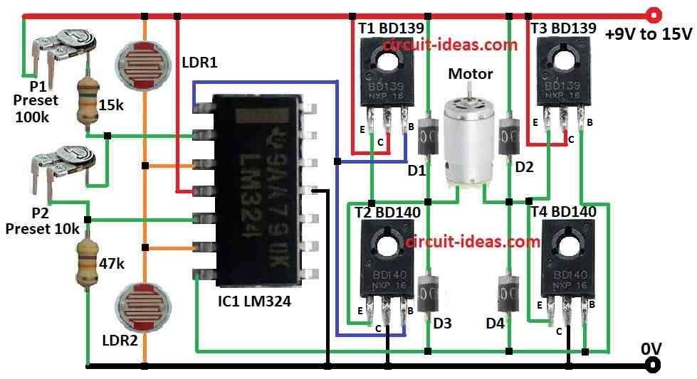
This solar tracker uses window comparator which stop motor when two LDRs light sensors get same sunlight.
When this happen both pin 3 and pin 6 get half of power voltage.
But when sun move light on LDRs change and then voltage also change.
Window comparator see this change and send signal to motor.
Motor move panel to follow sun again.
P1 and P2 are set to keep motor OFF when both LDRs get same light.
If LDR2 get less light than LDR1 voltage at point A become more than half power.
Then pin 1 go HIGH and transistor T1 and T4 turn ON and motor start moving.
If sun change angle again and voltage become less than half then pin 7 goes HIGH.
Transistor T2 and T3 turn ON and motor moves other way.
Better to use small motor with right voltage and max current of 300 mA.
This tracker follow sun only in flat horizontal direction.
If we want to follow sun up, down and vertical we will need second tracker circuit for that.
Sun Tracking Sensor

How to Build:
To build a Solar Tracker Circuit follow the below mentioned steps:
Build the Circuit:
- Connect LDR1 between plus power and pin 3 and pin 6 of IC LM324.
- Connect LDR2 between ground and pin 3 and pin 6 of same IC.
- Connect preset P1 100k between plus power and pin 2 using 15k resistor.
- Connect preset P2 10k between pin 2 and pin 5 of IC.
- Put 47k resistor between pin 5 and ground.
- Make H-bridge using 2 BD139 and 2 BD140 transistors.
- Connect motor in middle of H-bridge arms.
Set the System:
- Turn presets until motor stop when both LDRs get same sunlight.
Install the System:
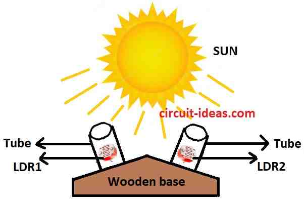
- Fix LDRs and solar panel on platform it must turn to follow sun.
Try and Fix:
- Take outside and check if it follow sun and If not adjust a little more.
Note:
- This is simple guide only we may need to change circuit or code for our own parts.
- Always be careful when working with solar and electric parts.
Conclusion:
Solar Tracker Circuit is very important part for solar power system it helps solar panels follow sun and get more sunlight so they work better.
Because it move panels all the time to face sun it make more energy and this way solar power become cheaper and more useful for long time.
Leave a Reply