Simple Low Power Ozone Generator Circuit use less power, as it make ozone gas from air and it uses electric spark to change oxygen to ozone.
Also, ozone help clean air and water and also kills the germs, but too much ozone is also not safe, it can be bad.
Circuit Working:
Parts List:
| Components | Values | Quantity |
|---|---|---|
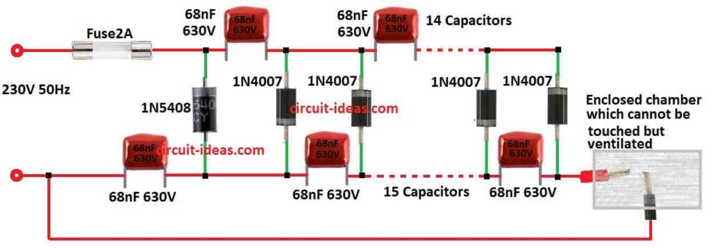
| Capacitors | PPC 68nF 630V | 29 |
| Semiconductors | Diode 1N5408 | 1 |
| Diodes 1N4007 | 28 | |
| Fuse 2A | 1 | |
| Touchproof chamber (see text) | 1 |
Ozone and ion can be made from air using sharp metal tip and flat metal plate and this make corona spark and create ozone and negative ions.
Also, ozone help remove smell, mold and germs and are good for damp places like basement, as it use cascade circuit to make high voltage from AC which are better and simple than flyback.
Board have capacitors on top, diodes under 15 caps on negative, 14 on positive, 29 diodes total.
High voltage parts are covered with epoxy to stop bad sparks; use 1N4007 diodes but first one must be strong like 1N5408 and if not then it will break fuse.
Box made with plastic glass and plastic screws are to stay safe, but spark part inside glass pipe are safe to touch but do not open.
At first we use pencil and brass but they got hot and then used steel nail and zinc ring which works better with air wind but with no fan needed.
Keep gap 5 to 7mm; in dark blue light means it working, also no spark in wet air is good.
Good for big room and is too strong for small room or long time use, as it takes only 0.35mA from 230V and turn OFF when no people are in room.
Ozone level is okay when air feel fresh but no strong smell, because if eyes get hurt or cough then there is too much ozone.
To test go out and come back smell the air and if smell strong it is too high.
Tips:
- Wear out after 6 to12 months.
- Zinc becomes zinc oxide is still okay.
- Clean tips once a year with steel washers will last longer.
Formulas:
The Cockcroft-Walton voltage multiplier gives high DC voltage from AC using capacitors and diodes and ideal output voltage formula:
Vout = 2 × n × Vpeak
where,
- Vout is the output voltage
- n is the number of stages for capacitor pairs
- Vpeak is the peak voltage of AC input
But in actual circuit output is lower due to diode drops and ripple.
More accurate formula:
Vout = 2 × n × Vpeak – (n + 1) × Vd – Vr
where,
- Vd is the voltage drop across each diode
- Vr is the ripple voltage
There is also a simple formula for capacitive multipliers:
Vout = N × Vin
where,
- N is the number of stages
- Vin is the input voltage
This is just a rough estimate, real output can change depending on load, frequency, diode quality, etc and also for correct results testing or simulation is better.
How to Build:
To build a Simple Low Power Ozone Generator Circuit follow the below mentioned steps for connections:
- Put sharp negative tip close to flat metal part with positive or neutral charge.
- Keep 5 to 7mm gap which is enough for visible and crackling corona but there should be no spark in humid air.
- Put capacitors on top of plain perforated board with no copper.
- Place diodes on the below of the board.
- Use high voltage transformer or circuit to boost AC grid voltage to high DC for corona.
- Build strong and safe case with plexiglass.
- Use UHU PLAST glue and polyamide screws and if using graphite, glue it in brass holder with graphite powder + lacquer mix.
- Better to use hardened steel nails and zinc washers it works well and is safer.
- Coat sharp edges with epoxy to stop unwanted corona discharge.
- Run the device and check if ozone and ions are produced.
- Adjust tip distance for best corona with soft blue glow and light sound is good.
- Clean device and sharpen tips once a year.
- Use stainless steel washers to last longer.
Important Note:
- This needs knowledge of electronics and high voltage safety and always be careful and follow safety steps.
Conclusion:
To conclude, Simple Low Power Ozone Generator Circuit is small and useful, as it makes ozone using high voltage with good for air cleaning, smell removal or water treatment.
Also, it includes high voltage parts like ozone chamber, controls and safety setup.
Leave a Reply