• Skip to primary navigation
  • Skip to main content
  • Skip to primary sidebar

Circuit Ideas for You

Get free circuit ideas online.

  • Home
  • Privacy Policy
  • About
Home » Simple TV, Video Transmitter Circuit

Simple TV, Video Transmitter Circuit

Last updated on 31 May 2025 by Admin-Lavi Leave a Comment

Have anyone ever wished to construct its own small television station?

This article is for hobbyists who want to make a simple transmitter to broadcast videos inside your house.

The transmitter uses a special coil and capacitor to pick a channel between 37 and 50 on the old fashioned TV dial UHF band, 470 to 855 MHz.

The exact channel depends on the size of the coil and capacitor.

WARNING: Building a TV transmitter may be illegal in some regions.

Check the rules before trying this project.

What is a TV, Video Transmitter Circuit:

A TV and video transmitter circuit is an electronic circuit that enables the transmission of audio and video signals wirelessly from a source device such as a camera or DVD player to a television or video receiver.

This type of circuit is commonly used in applications like wireless surveillance cameras, video baby monitors or hobbyist projects where video signals need to be transmitted over short distances.

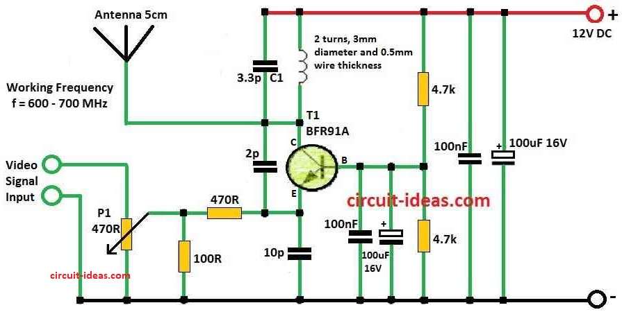
Circuit Working:

Simple TV, Video Transmitter Circuit Diagram

Parts List:

ComponentDescriptionQuantity
ResistorsAll resistors are 1/4 W CFR
470Ω1
100Ω1
4.7k2
Preset470Ω1
Capacitors
Ceramic3.3pF1
2pF1
10pF1
100nF2
Electrolytic100μF 16V2
Semiconductors
TransistorBFR91A1
InductorCoil, air core, 2 turns, 3mm diameter using 0.5mm thick super enameled copper wire1

The heart of the TV, video transmitter circuit is a simple oscillator built around a high frequency NPN transistor such as BFR90, BFR91A, BFR92 or BFR93.

In this example a planar TO50 enclosure contains the selected transistor.

The transistor functions as an active component that generates a high frequency oscillation.

In the LC circuit the values of the inductor coil and capacitor C1 are the main factors that decide the oscillators frequency.

The resonant frequency is tuned within the correct UHF range which is 470 to 855 MHz by adjusting the values of the coil and C1.

This enables the RF signal to be transmitted on particular TV channels.

The antenna is just a normal wire about 5 cm (2 inches) long.

The RF signal is transmitted since the antenna and oscillator are directly connected.

The oscillators carrier frequency is changed using the video signal which is captured from a source such as a security TV camera or a camera with a video output.

The carrier signals amplitude is changed during the modulation process to match the video signal.

The circuit requires a voltage supply in the range of 5 to12V.

The power supply boots the oscillator allowing it to generate the oscillating RF signal.

The circuit includes a potentiometer P1 to control the modulation depth.

The level to which the amplitude of the carrier signals varies in response to the video signal is known as the modulation depth.

Modulation depth is influenced by P1 modification which is necessary to improve image quality.

Once the transmitter is powered up the video source it is than connected and the circuit is manually tuned.

Finding the transmitted signal on a analog TV within the UHF band which is usually in the 37th to 50th channel or the 600 to 700 MHz range which is the tuning process.

Formulas:

Below are the formulas for Simple TV, Video Transmitter Circuit:

The frequency of the television transmitter in this oscillator circuit is calculated using the formula for the resonant frequency of an LC circuit.

The resonant frequency (f) is given by:

f = 1 / 2π√LC

where:

  • Resonant frequency is indicated by f.
  • The mathematical constant π is about 3.14159.
  • L is the inductor coils inductance.
  • C represents the capacitor C1s capacitance.

The schematic diagram is used to create the values of L and C in the TV video transmitter circuit.

The transmitters working frequency is used to find the resonant frequency.

Also the modulation depth M is calculated using the following formula and provided as a proportion:

M (%) = ( Vmax − Vmin / Vmax + Vmin ) × 100

where:

  • M is the modulation depth in percentage
  • Vmax​ is the maximum amplitude of the modulated signal
  • Vmin​ is the minimum amplitude of the modulated signal.

The potentiometer P1 in the television transmitter is used to modify the modulation depth in order to produce the desired image quality.

The modulation depth is affected by the modulated carrier signals amplitude which can be successfully controlled by adjusting P1.

The frequency and modulation features of the television transmitter are mathematically explained because to these formulas which permits careful modification and improvement throughout construction.

How to Build:

To build a Simple TV, Video Transmitter Circuit following steps are required for connections:

  • Choose an NPN transistor with a high frequency that operates well with an oscillator circuit.
  • Add BFR90, BFR91A, BFR92 or BFR93 as required.
  • Put the transistor of choice into a TO50 enclosure that is planar.
  • For information on the coil and C1 values see the schematic diagram.
  • These parts gauge the transmitters frequency range.
  • Achieve a frequency within the necessary UHF range of 470 to 855 MHz by setting the coil and C1.
  • To act as the antenna directly connect a wire that is about 5 cm i.e 2 inches long to the oscillator circuit.
  • Connect the transmitter to the 5 to12V voltage supply.
  • Reduce the length of live connections to reduce excessive inductance and capacitance.
  • To minimize parasitic effects use 100nF decoupling capacitors as near to the transistor as possible.
  • 50 Hz to several hundred MHz frequencies are easily blocked by adding parallel 100uF electrolytic capacitors.

Adjustment:

  • To control the modulation depth include potentiometer P1 in the circuit.
  • To get the best possible image quality one needs to adjust P1.
  • High contrast can be produced by excess modulation whereas alignment problems may occur by not enough modulation.

Tuning Procedure:

  • Activate the transmitter.
  • Connect the transmitter to the video source.
  • Security TV cameras and cameras with video output are examples of suitable sources.
  • On an analog television manually look for the sent signal.
  • For the best coverage look in the 37th to 50th channel or the 600 to 700 MHz range.
  • Video transmissions without audio could be skipped by certain TVs with auto tuning features.
  • Do a manual search for complete coverage if this happens.

Caution:

  • Understand the legal problems of using the UHF television band for broadcasting.
  • In some nations broadcasting is strictly banned.
  • Any legal issues arising from unlicensed broadcasting are not the writers responsibility.
  • Begin with this project at ones own risk and by obeying the local laws.

Conclusion:

It is important to keep in mind that the particular needs and desired usage affect the design of TV and video transmitter circuits.

Commercial video transmitters with built-in audio capabilities, multiple channels, frequency bands and increased broadcast strength are also available.

Also users should be aware of local radio frequency broadcast rules.

References:

Datasheet BFR91A

Filed Under: Transmitter Circuit

About Admin-Lavi

Lavi is a B.Tech electronics engineer with a passion for designing new electronic circuits. Do you have questions regarding the circuit diagrams presented on this blog? Feel free to comment and solve your queries with quick replies

Previous Post: « 220V Power Line Communication Remote Control Circuit
Next Post: Simple ESR Meter Circuit »

Reader Interactions

Leave a Reply Cancel reply

Your email address will not be published. Required fields are marked *

Primary Sidebar

Categories

  • Alarm Circuits (30)
  • Amplifier Circuits (67)
  • Arduino Projects (29)
  • Audio Circuits (93)
  • Automobile Circuits (19)
  • Battery Charger Circuits (48)
  • Free Energy (13)
  • Heater and Temperature Controllers (9)
  • Indicator Circuits (38)
  • Inverter Circuits (13)
  • LDR Circuits (13)
  • LED and Lamps (111)
  • Meters and Testers (27)
  • Motor Controllers (18)
  • Oscillator Circuits (32)
  • Power Supply Circuits (91)
  • Remote Control Circuits (6)
  • Security and Protection (23)
  • Sensors and Detectors (71)
  • Solar Circuits (16)
  • Timer Circuits (27)
  • Transistor Circuits (56)
  • Transmitter Circuit (12)
  • Tutorials (4)
  • Water Level Controller (4)

Copyright © 2025 | New Circuit Ideas