Normal digital clock use RTC chip or manual setting, but the problem is RTC needs drift and reset.
So here Arduino Based GPS Digital Clock Circuit solves the problem; GPS talk with satellite and always give exact time, then Arduino read GPS time and show on LCD.
So clock is never wrong, as it always auto update from sky.
Arduino Code:
#include <LiquidCrystal.h>
#include <TinyGPS.h>

LiquidCrystal lcd(7,6,5,4,3,2);
TinyGPS gps;

void setup(){
lcd.begin(16,2);
Serial.begin(9600);
}

void loop(){
while(Serial.available()>0){
if(gps.encode(Serial.read())){
int hour, minute, second;
unsigned long date, time;
gps.get_datetime(&date,&time,0);
hour = (time/1000000);
minute = (time%1000000)/10000;
second = (time%10000)/100;
lcd.setCursor(0,0);
lcd.print("Time: ");
lcd.print(hour);
lcd.print(":");
lcd.print(minute);
lcd.print(":");
lcd.print(second);
}
}
}
Coding Explanation:
- LiquidCrystal library control LCD.
- TinyGPS library decode GPS data.
- Serial begin connect Arduino with GPS.
- gps.get_datetime give UTC date and time.
- The circuit separates the time data into hours, minutes and seconds.
- LCD print values on display.
Circuit Working:
Parts List:
| Components | Quantity |
|---|---|
| Arduino Uno | 1 |
| GPS Module | 1 |
| LCD Display 16×2 | 1 |
| Potentiometer 1k | 1 |
To begin with, circuit working is quite simple and Arduino controls the full process.
Then GPS module sends data from satellite to Arduino and GPS receive signal from satellite; also it send NMEA data string to Arduino.
After that, Arduino read using serial and TinyGPS decode and extract date and time; now Arduino print hour minute second on LCD.
Finally, output is digital clock which is always correct with GPS.
Formulas:
The following formula helps calculate the values used in the GPS Digital Clock Circuit.
Time = UTC from GPS satellites.
hour = time/1000000
minute = (time%1000000)/10000
second = (time%10000)/100
Example if time = 15230500
hour = 15
minute = 23
second = 05
How to Build:
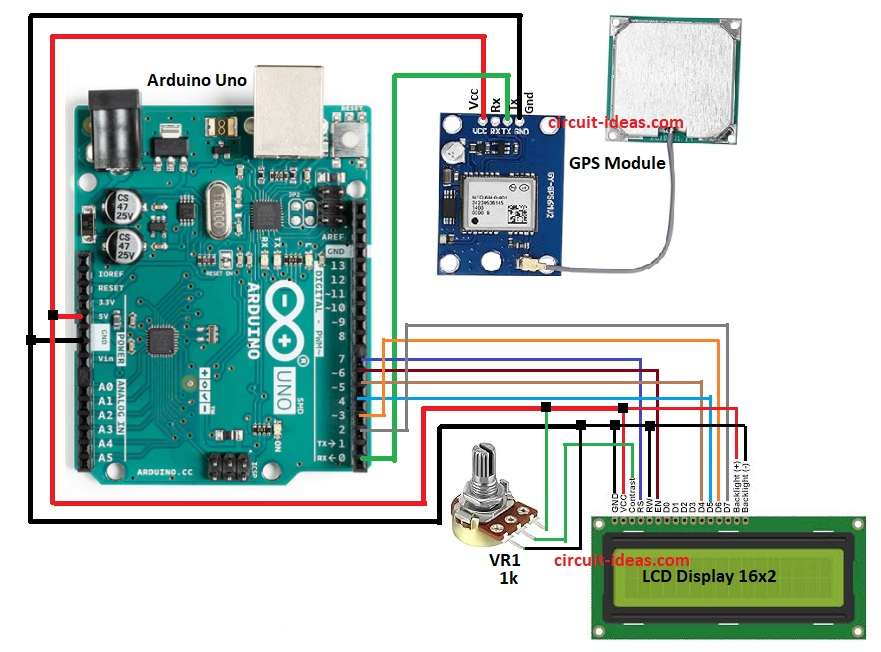
To build a Arduino Based GPS Digital Clock Circuit follow the below mentioned connection steps:
- First, take all the parts as per the circuit diagram above.
- Next, connect the GPS module GND pin to Arduino GND, the GPS VCC pin to Arduino 5V, and the GPS TX pin to Arduino RX pin 0 and leave the GPS RX pin unconnected because the circuit does not use it.
- Then LCD pin 1 GND pin go to GND of Arduino, LCD pin 2 VCC go to +5V Arduino and LCD pin 3 Contrast go to middle pin of 1k pot VR1, one end go to 5V and other to GND.
- After that, LCD pin 4 RS connect to Arduino D7, LCD pin 5 RW connect to GND of Arduino and LCD pin 6 EN connect to Arduino D6.
- Further, LCD pin 11 D4 connect to Arduino D5, LCD pin 12 D5 connect to Arduino D4 and LCD pin 13 D6 connect to Arduino D3.
- Finally, LCD pin 14 D7 connect to Arduino D2, LCD pin 15 LED+ connect to +5V and LCD pin 16 LED- go to GND of Arduino.
Conclusion:
To conclude, the Arduino Based GPS Digital Clock Circuit offers a simple and accurate solution and it does not require an RTC module.
The clock automatically adjusts its time from GPS satellites; also this circuit supports time based projects and provides a low cost, easy to build solution.
Leave a Reply