This article shows how to build a Two LED Temperature Indicator Circuit, as it is easy and cool project and we can use this circuit for many things, like checking water shower when it is not too hot, so no damage can happen.
Furthermore, also be sure computer parts, amplifier, heater and even car water tank do not get too hot.
What is a Two LED Temperature Indicator Circuit:
People call the simple electronic circuit that shows temperature changes a “two LED temperature indicator.” and this circuit uses two LEDs to indicate temperature levels and helps check the temperature of an object or place.
Here, LEDs work like a simple signal, one LED for low temperature and other for high or they can show different temperature levels.
Thus, this article gives full guide with easy steps to make color temperature indicator using two LED.
Circuit Working:
Parts List:
| Components | Values | Quantity |
|---|---|---|
| Resistors | All resistors are 1/4 W CFR | |
| 1k | 1 | |
| 10k | 2 | |
| Preset 330k | 1 | |
| Thermistor NTC 10k | 1 | |
| Semiconductors | ||
| Transistors BC547 | 2 | |
| LEDs Green 5mm 20mA | 1 | |
| Red 5mm 20mA | 1 |
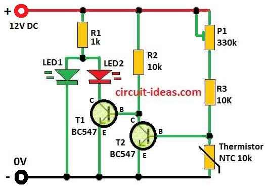
In this temperature circuit with two LEDs a green LED1 blink when temperature is low and red LED2 turn ON when temperature is high, also this circuit work by using thermistor Th1 and its resistance change with temperature.
Also, when temperature is low Th1 resistance goes high and this make voltage at transistor T2 base go up so T2 turn ON.
Then T1 turn OFF and current goes to LED1 and so green LED light up.
Further, when temperature goes high Th1 resistance goes low and voltage at T2 base goes down and T2 turns OFF.
Now T1 turn ON and red LED2 lights up.
To be sure LED1 work good so we add one diode like 1N4007 if LED voltage drop is not enough.
Both LEDs use same resistor R1 and because red LED2 have lower voltage drop and green LED1 stay OFF when red one is ON.
So, we used potentiometer P1 to set the temperature level when LED changes and if we do not get correct temperature then change value of P1 or R3.
Formulas and Calculations:
Below is formula and calculation for Two LED Temperature Indicator Circuit and this formula help to find temperature using resistance:
1/T = A × ln(R) + B × ln(R)² + C × ln(R)³ + D
where:
- T is temperature in Kelvin K
- R is thermistor resistance in ohms Ω
- A, B, C, D are special values which are constants from thermistor datasheet
These A, B, C, D values come from thermistor datasheet and we need to check that for correct values, so after that we can put value in formula and solve to get temperature.
How to Build:
To build a Two LED Temperature Indicator Circuit follow the below steps:
- First, as shown in the circuit diagram connect LED1 and LED2 with thermistor Th1 and transistors T1 and T2.
- Next, choose resistor values for R1, R2 and R3 based on what temperature range we want and LED details.
- After that, use potentiometer P1 to set the temperature point where LED should change.
- then if needed add one diode like 1N4007 in series so LED1 get enough voltage drop to work.
- Hence, after turning ON the circuit watch how LEDs react at different temperatures.
- Finally, if temperature is not showing correct then adjust P1 and change resistor values to fix it..
Conclusion:
Overall, to build a Two LED Temperature Indicator Circuit we should keep in mind this is just a basic idea.
Finally, circuit design can be different and it will depend on what user needs and chooses.
Also, for advanced temperature check people use digital temperature sensors which give digital output.
Leave a Reply