Pulse frequency counter count signal in hertz (Hz).
It is an important tool in electronics.
Now Arduino and other microcontroller make counter easy and cheap.
This article for Simple Pulse Frequency Counter Circuit with Arduino show how to make this easy circuit with few parts.
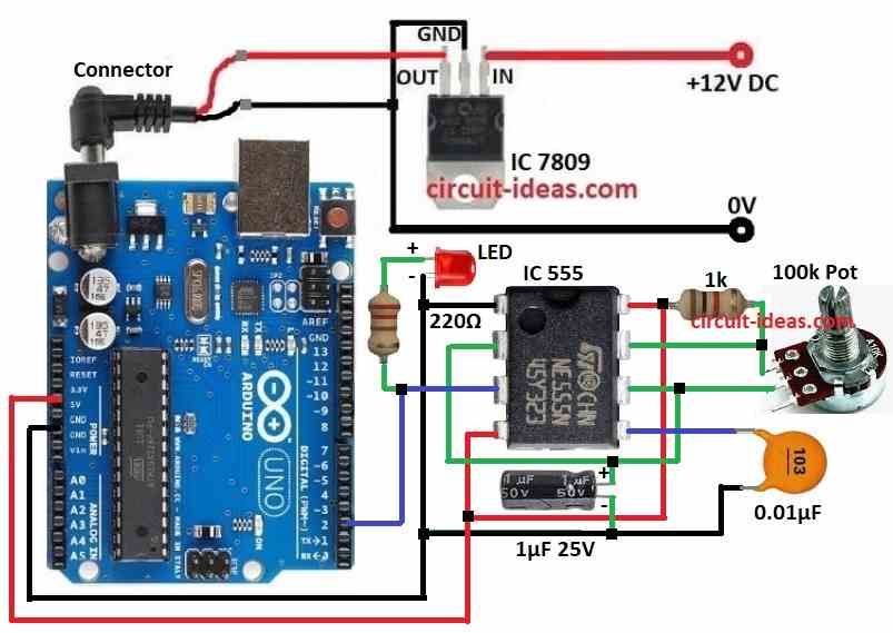
We have used IC 555 to make pulse, IC 7809 for control voltage and one LED to show signal.
Code:
[Arduino]          [IC 555]          [IC 7809]
   Pin 2 <------- Pin 3

volatile unsigned long pulseCount = 0;
unsigned long frequency = 0;

void setup() {
    Serial.begin(9600);
    pinMode(2, INPUT); // Pin connected to IC 555 output
        attachInterrupt(digitalPinToInterrupt(2), countPulse, RISING);
}

void loop() {
    pulseCount = 0; // Reset pulse count
    interrupts(); // Enable interrupts
    delay(1000); // Count pulses for 1 second
    noInterrupts(); // Disable interrupts

    frequency = pulseCount; // Store the frequency count
    Serial.print("Frequency: ");
    Serial.print(frequency);
    Serial.println(" Hz");
    digitalWrite(13, frequency > 0 ? HIGH : LOW); // Turn LED on if frequency > 0
}

void countPulse() {
    pulseCount++; // Increment pulse count
}
Code Explanation:
- frequency save the frequency value.
- pulseCount count how many pulses come.
- setup set pin modes, start serial and make interrupt for count pulse when signal goes up.
- loop send data to serial monitor, find frequency and reset pulse count every 1 second.
- Also it uses pulse to turn LED ON/OFF.
- countPulse() is interrupt function and it adds 1 to pulseCount when pulse happen.
Circuit Working:
Parts List:
| Component | Value | Quantity |
|---|---|---|
| Resistors | 1k 1/4 watt | 1 |
| 220Ω 1/4 watt | 1 | |
| Potentiometer 100k | 1 | |
| Capacitor | Electrolytic 1μF 25V | 1 |
| Ceramic 0.01μF | 1 | |
| Semiconductors | Arduino Uno Board | |
| IC 7809 Voltage Regulator | 1 | |
| IC 555 Timer For pulse generation | 1 | |
| LED Red 5mm 20mA any color | 1 |
This pulse counter project work good because of IC 7809.
Arduino Uno and IC 555 need stable power to work.
IC 7809 take high voltage like 12V and give steady 9V output.
Arduino for reading pulses and IC 555 for making pulses both need this 9V to work right.
Potentiometer control the pulse speed (frequency) from IC 555 in astable mode and it make square wave signal.
Arduino count pulses by checking rising edge of square wave using interrupt.
Arduino uses this frequency to turn LED ON/OFF and show number on serial monitor.
Formulas:
Formula to find frequency from pulse time is:
Frequency (Hz) = 1,000,000 / Pulse Duration (µs)
Pulse duration is how long one pulse stays.
It is measured in seconds (s).
Example: 0.001 second = 1 millisecond (ms).
Sometimes it mean total time of many pulses in some time range.
Frequency means how many times something happen in 1 second.
In pulse signal it mean how many pulses in 1 second.
Pulse time is often in microseconds (µs) so we use 1,000,000 to change µs to seconds.
This is useful because microcontrollers often work in microseconds.
How to Build:
For Building a Simple Pulse Frequency Counter Circuit with Arduino follow the below steps:
- Take all parts shown in circuit diagram.
- Use IC 7809 to give steady 9V DC to Arduino same as in diagram.
- Connect pin 1 of IC 555 to Arduino GND.
- Connect pin 2 to pin 6 of IC 555.
- Connect pin 3 of IC 555 to Arduino digital pin 2.
- Put 220Ω resistor and LED between pin 3 and GND.
- Connect pin 4 and pin 8 of IC 555 to 5V on Arduino.
- Put 0.01µF capacitor from pin 5 to GND for stable signal.
- Put 1µF capacitor from pin 6 to GND.
- Connect 1k resistor from pin 7 to +V positive power.
- Connect 100k potentiometer one leg to pin 7 and middle leg to pin 6.
Conclusion:
This Building a Simple Pulse Frequency Counter Circuit with Arduino is a simple and fun project to learn frequency and signal checking.
Arduino count pulses and IC 555 make pulse signal.
Together they make useful tool for testing and checking signals.
This circuit is a good project to learn basic electronics and how Arduino help in many small tasks.
Leave a Reply