Designing a UJT-Based Audio Tone Generator Circuit is easy and fun.
It makes music sound like small instrument.
It use UJT as relaxation oscillator.
Push buttons change frequency with different notes.
Sound goes to speaker after amplifier.
Press button, tone change and w UJT 2N2646 will make right frequency.
Transistor boost the sound from speaker.
Circuit is good for students, hobby people and sound experiment.
It uses 9V battery or 9V DC power.
Circuit Working:
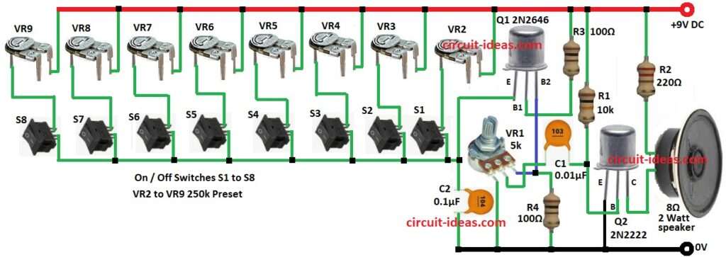
Parts List:
| Component Type | Specification | Quantity |
|---|---|---|
| Resistors (All resistors are 1/4 watt unless specified) | 10k | 1 |
| 220Ω | 1 | |
| 100Ω | 2 | |
| Potentiometer 5k | 1 | |
| Presets 250k | 8 | |
| Capacitors | Ceramic 0.01µF | 1 |
| Ceramic 0.1µF | 1 | |
| Semiconductors | UJT 2N2646 | 1 |
| Transistor 2N2222 | 1 | |
| Speaker 8Ω | 1 | |
| On / Off Switches | 8 |
This is sound maker using UJT 2N2646 is very cool circuit.
Press button and get different sound and each button play tune we like.
UJT 2N2646 act as oscillator and make pulses high and low.
How it work:
Press S1 to S8 switches and use VR2 to VR9 presets to set C2 charge time.
C2 charge with UJT ON and C2 gets discharge fast.
Repeat and make sound by RC timing.
Change VR2 to VR9 and change frequency.
Each button have different note.
It sound is weak then use Q2 2N2222 to boost.
Then signal goes to 8Ω speaker and we hear sound.
Formulas:
UJT Sound Circuit Frequency Formula:
To find sound frequency:
f = 1 / ( R × C × ln(1 / (1 – η)) )
where:
- f is the frequency in Hz
- R is the resistance in ohms Ω
- C is the capacitance in farads F
- η is the UJT standoff ratio for 2N2646 which is about 0.6 to 0.8
- ln is the natural log
How to Build:
For Designing a UJT-Based Audio Tone Generator Circuit following steps should be followed:
- Q1 emitter connects to one end of C1 and other end of C1 goes to GND
- Q1 B1 pin connects to +V through resistor R3
- Q1 B2 pin connect one pin of VR1 other pin of VR1 and GND
- R4 connect between B2 of Q1 and pot VR1
- Base of Q2 connects to one end of C1 and C1 also goes to VR1
- R1 connect between base of Q2 and C1 and other end of R1 connects to +V
- Q2 emitter goes to GND
- Q2 collector connects to one end of 8Ω speaker and other end of speaker go to R2 and R2 go to +V
- Add switches from S1 to S8
- Connect presets VR2 to VR9 to each switch and adjust for tuning musical notes.
Conclusion:
This Designing a UJT-Based Audio Tone Generator Circuit shows how UJT works as oscillator.
It is good for learning how RC timing changes sound.
Circuit is easy and best for beginners, hobby people to make fun sounds.
Leave a Reply