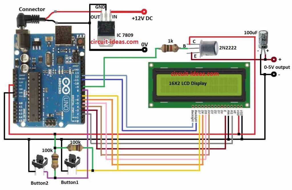
This project DIY Variable Power Supply Circuit shows how to use an Arduino Uno board to generate a variable power source.
A transistor and resistors are used to modify the circuits steady 9V output, which is produced by an IC 7809 voltage regulator.
A 100uF capacitor filters the output voltage.
The output voltage may be manually adjusted using two pushbuttons.
Actual feedback on the current output voltage is provided by an LCD monitor.
Coding with Explanation:
#include <LiquidCrystal.h>

LiquidCrystal lcd(12, 11, 5, 4, 3, 2);

int button1 = 7;
int button2 = 8;
int pwmPin = 9;

int dutyCycle = 0;

void setup() {
  lcd.begin(16, 2);
  lcd.print("Variable Power Supply");
  pinMode(button1, INPUT);
  pinMode(button2, INPUT);
  pinMode(pwmPin, OUTPUT);
}

void loop() {
  if (digitalRead(button1) == HIGH) {
    dutyCycle++;
    if (dutyCycle > 255) {
      dutyCycle = 255;
    }
  } else if (digitalRead(button2) == HIGH) {
    dutyCycle--;
    if (dutyCycle < 0) {
      dutyCycle = 0;
    }
  }

  analogWrite(pwmPin, dutyCycle);

  lcd.setCursor(0, 1);
  lcd.print("Voltage: ");
  lcd.print(dutyCycle * 9 / 255);
  lcd.print("V");
  delay(100);
}- Include is the Liquid Crystal library for controlling LCD displays.
- Setup prints a greeting, initializes the LCD screen, and configures the input and output pins.
- Loop constantly assesses the push buttons condition.
- The duty cycle rises when button 1 is pressed and falls when button 2 is pressed.
- The PWM output is then controlled by the duty cycle, which modifies the voltage.
- The LCD shows the output voltage at this moment.
Circuit Working:
Parts List:
| Component | Quantity |
|---|---|
| Arduino Uno Board | 1 |
| LCD 16X2 | 1 |
| IC 7809 | 1 |
| Tactile switches | 2 |
| Transistor 2N2222 | 1 |
| Resistors 1k 1/4 watt | 1 |
| Resistors 100k 1/4 watt | 2 |
| Capacitors 100µF 25V | 1 |
The variable power supply circuit is powered by the Arduino Uno.
TThe output of the 7809 is set at 9V.
The output voltage is fixed as long as the input voltage is more than 9V since it is not adjustable.
The output voltage is lowered by the voltage divider to a value that the Arduino can read, between 0 and 5V.
Pin 9 of the Arduino Uno produces a PWM signal.
Driven by the PWM signal, the transistor functions as a switch.
The scaled voltage is read by the Arduino and shown on the LCD.
The scaled reading is converted to the real output voltage using the voltage divider factor.
Resistor 1k control the transistors base current, which in turn affects the transistors conduction.
To stabilize the output voltage, connect an 100µF capacitor between the output pin 0-5V and ground.
To cut down on noise, the capacitor 100µF filters the output voltage.
The current output voltage is shown on the LCD monitor.
How to Build:
To build a DIY Variable Power Supply Circuit using Arduino follow the below mentioned steps for connections:
- Gather all the components as shown in the above circuit diagram.
- Connect a regulated IC1 7809 to provide a regulated 9V DC to the Arduino board.
- Connect Tactile switch button1 one leg from pin 7 on the Arduino board and other leg to ground.
- Connect Tactile switch button2 one leg from pin 8 on the Arduino board and other leg to ground.
- Connect one 100k resistor between pin 7 and positive 5V on Arduino board.
- Connect other 100k resistor between pin 8 and positive 5V on Arduino board.
- Connect R/W on the LCD display with the ground supply on the Arduino
- Connect Transistor 2N2222 collector to the 5V power supply, connect base to pin 9 on Arduino board through resistor 1k, and connect emitter to 0-5V output.
- Connect capacitor 100µF positive leg to 0-5V output and negative leg to negative of output.
LCD Connections to Arduino Uno Board:
| Arduino Pin | LCD Pin | Function |
|---|---|---|
| 2 | RS | Register Select |
| 3 | EN | Enable |
| 4 | D4 | Data Bit 4 |
| 5 | D5 | Data Bit 5 |
| 6 | D6 | Data Bit 6 |
| 7 | D7 | Data Bit 7 |
| 11 | Backlight+ | Positive supply for backlight |
| 12 | Backlight- | Negative supply for backlight |
| 5V | VCC | Positive supply for LCD |
| GND | GND | Ground for LCD |
Conclusion:
This project shows how to use an Arduino Uno to create a variable power source in a simple and efficient manner.
Within a specific range, the output voltage may be changed by varying the PWM signals duty cycle.
An important source of feedback for keeping an eye on the output voltage is the LCD display.
By including features like automated voltage control or a more accurate voltage measurement, this project may be improved even further.
Leave a Reply