To Design Crystal Oscillator Circuit we need know some basic things; first use crystal to make steady frequency and then choose right crystal and connect with other parts like resistor and capacitor.
After that, be sure circuit give right signal for our device.
Therefore, these easy steps help us build good working circuit.
Circuit Working:
Let us learn about this circuit with help of above diagram:
Crystal Oscillators is like an Heartbeat for Electronics, as these crystal oscillator is circuit that uses special mineral called quartz and these Quartz show piezoelectric effect and it vibrate when voltage come and give small voltage when vibrated.
Also, because of this the quartz crystal makes a very steady signal, as the circuit uses this to give constant frequency.
Hence, this frequency does not change much with heat or environment.
Why Important?
Crystal oscillator gives stable timing signal and is very useful in electronic watches, microcontrollers and microprocessors and clock circuits
How it works:
Quartz work like transducer and it changes electricity into vibration and back and this crystal stay between two metal plates and the circuit parts help keep it vibrating.
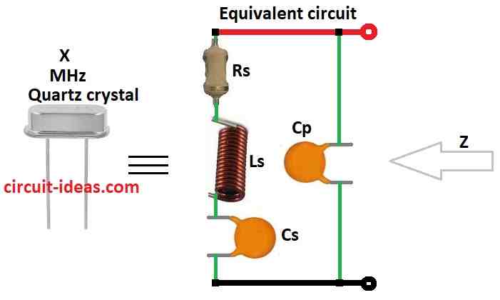
Inside model of crystal:
Series RLC part show:
- Rs as resistance
- Ls as inductor means stiffness
- Cs as capacitance inside crystal
- Parallel Cp as capacitance between metal plates
Designing for right frequency:
There are two main types: Series resonance and Parallel resonance and to get correct frequency we need to choose right external parts like resistors, capacitors.
Formulas:
Series Resonance Formula:
fs = 1 / 2π√(Ls * Cs)
where,
- fs is the resonance frequency in Hz
- Ls is the inductor value in henries H
- Cs is the capacitor value in farads F
What it mean:
Crystal vibrate most at this frequency and inductor and capacitor pass energy back and forth.
Also, at this point circuit allow max current and is at very low resistance means impedance and this called resonance.
Angular frequency (speed of phase change):
ωs = 2πfs
How we get formula:
At resonance:
XL = XC → ωLs = 1 / ωCs
Solve for ω convert to fs and fs = 1 / 2π√(Ls * Cs)
Parallel Resonance Formula:
fp = 1 / [2π√(Ls * (Cp * Cs / (Cp + Cs)))]
where,
- fp is the parallel resonance frequency in Hz
- Cp and Cs are the two capacitor values
- Ls is the inductor in H
What happens here:
Inductor and two capacitors cancel each other at one frequency of fp and this time impedance is very high means opposite of series.
Hence, circuit block current here with less feedback.
Capacitance in parallel circuit:
1 / Ctotal = 1 / Cp + 1 / Cs
Result uses the above formula.
Choosing Right Type:
Series Resonance:
- Stronger signal
- Good for keeping oscillation going
Parallel Resonance:
- High impedance
- Good when need reduce feedback
Both need right Ls, Cs, Cp values to give correct frequency, so use carefully to design oscillator for clocks, microcontrollers etc.
Crystal Oscillator circuit diagram:
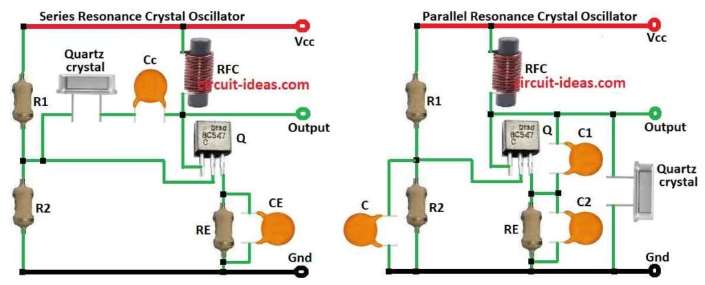
Building Crystal Oscillators: Series vs Parallel Resonance
We can build a crystal oscillator circuit in two main ways, and each configuration produces a different type of resonance:
1. Series Resonance Oscillator:
Use transistor in common emitter mode.
We place the crystal and coupling capacitor between the base and collector; the base controls the current flow between the collector and emitter and amplifies the signal.
Output comes from collector and then crystal gives series resonance here.
2. Parallel Resonance Clock:
Same common emitter transistor used, but now crystal is between collector and emitter.
We take the output from the collector and this configuration produces parallel resonance.
Key Point:
- Even with the same transistor configuration, the placement of the crystal and capacitors show whether the circuit operates in series resonance or parallel resonance mode.
Main Parts and Device used in Crystal Oscillators:
Crystal oscillator use one main switching part in center and this can be: BJT (bipolar junction transistor), FET (field effect transistor), MOSFET (metal oxide field effect transistor)
Therefore, these parts amplify signal and help keep the oscillation going.
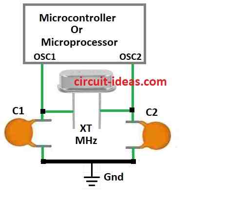
Working with Microcontrollers and Microprocessors:
Many new microcontrollers and microprocessors have built-in pins for crystal oscillator, so no need for extra oscillator circuit.
Also, these pins work with specific crystal frequency to keep the IC chip working properly.
Conclusion:
Overall, How to Design Crystal Oscillator Circuit uses quartz crystal to give steady and correct signal like metronome in music.
Furthermore, we can design different circuits to generate the required frequency, as these circuits also play an important role in providing accurate timing for devices ranging from watches to computers.
As a result, because they are flexible and can be built-in in microchips, they are must have part in modern electronics