This Long Range FM Transmitter Circuit (2km) send voice or music on FM radio.
It can cover up to 2 km range with good antenna.
It use small microphone to take sound and then circuit make signal.
Signal goes to antenna and any FM radio can catch it.
It runs on 12V battery with simple parts and is easy to make.
Circuit Working:
Parts List:
| Category | Item | Quantity |
|---|---|---|
| Resistors (All resistors are 1/4 watt unless specified) | R1 10k, R2 1k, R3 22k, R4 2.2k, R5 68Ω, R6 68k, R7 18Ω, R8 2.2k, R9 1k | 1 each |
| Capacitors | Ceramic C2 0.01µF, C3 1nF, C4 8.2pF, C5 0.1µF, C6 0.1µF, C7 1nF, C8 1nF, C9 1nF, C10 0.01µF | 1 each |
| Electrolytic C1 2.2µF 25V, C11 100µF 25V | 1 each | |
| Trimmers | Trimmer VC1 22p, VC2 22p, VC3 22p, VC4 22p, VC5 22p, VC6 40p, VC7 40p | 1 each |
| Semiconductors | IC 7809 | 1 |
| Transistor T1 BF494, T2 BF200, T3 2N2219, T4 2N3866 | 1 each | |
| Electret MIC | 1 | |
| Coil L1 4 turns, Coil L2 6 turns, Coil L3 6 turns, Coil L3 6 turns, Coil L4 5 turns, Coil L5 7 turns | 1 each | |
| Load Antenna 50Ω | 1 |
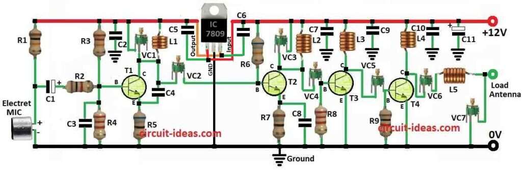
This FM transmitter have 4 stages.
T1 BF494 make oscillator with mic for voice.
Signal goes to small amp T2 BF200 and then driver T3 2N2219 or 2N5109 and last power amp T4 2N3866 or 2N4427.
Driver class C is preamp class A and final class C give strong RF.
Use 50Ω dipole or ground plane antenna.
VC1 to VC7 tune frequency 88 to 108 MHz and for best range.
Power 12V battery and regulator 7809 gives stable 9V.
Coils L1 to L5 is made by 20SWG wire and from 4 to 7 turns.
How to Build:
To build a Long Range FM Transmitter Circuit (2km) we need to follow the below mentioned steps:
- See circuit and put all parts on PCB.
- First solder small parts and then transistors BF494, BF200, 2N2219, 2N3866.
- Mic goes to input of BF494 oscillator.
- Connect coils L1 to L5 same as design.
- Power by 9V or 12V battery and use 7809 regulator for stable 9V.
- Tune VC1 to VC7 with coils for 88 to108 MHz and for long range.
- Fix heat sink on final transistor and set 50Ω dipole or ground plane antenna.
Conclusion:
This Long Range FM Transmitter Circuit (2km) is made to send FM signal very far or even many kilometers.
It give strong power, clear sound, good antenna, stable frequency and follows radio rules.
To make this circuit we need to build carefully and adjust it well so it works good and does not break any law.
Hi Lavi
Thanks for the schematic, do you have a PCB layout? If so, I’d appreciate if you can share it.
Also can I use BF199 instead of BF200 as I have plenty?
Hi Sina,
I am sorry i do not have a PCB layout for this circuit but yes, you can use BF199 instead of BF200 in long-range FM transmitter, but it might not go as far or sound as clear, BF199 will still work just try it out and adjust the inductors and capacitor values to make it work best!
Thanks, keep up with your good work!
Thanks take care….
Be cognizant that a transemitter like this design is not permitted to legall in any place. Without phares-looked-loop frequently will end up begin down slipping with calor. Extra to badly constricted circles will emitt snignal in dangeror air-band frequently. BEAWARE.
thanks for your reply, the article is already showing necessary warning which is now marked in red..