No need to check water with normal stick, because this Water Level Indicator Circuit with Digital Display use sensor to check water level.
Then it show number from 0 to 9 on small screen, like mini calculator; so we can always see what level the water is in the tank.
Hence, with this circuit, there is no need to guess.
Circuit Working:
Parts List:
| Components | Values | Quantity |
|---|---|---|
| Resistors | 560k 1/4 watt | 9 |
| 12k 1/4 watt | 4 | |
| 33k 1/4 watt | 4 | |
| 470Ω 1/4 watt | 7 | |
| Semiconductors | IC 74HC147 | 1 |
| IC CD4511 | 1 | |
| Transistor BC547 | 4 | |
| 7 segment common cathode display | 1 | |
| Water Tank | 1 |
Water tank level circuit usually uses small LED lights, but in this article we have made a digital type.
It uses 7 segment display to show number 0 to 9 for water level.
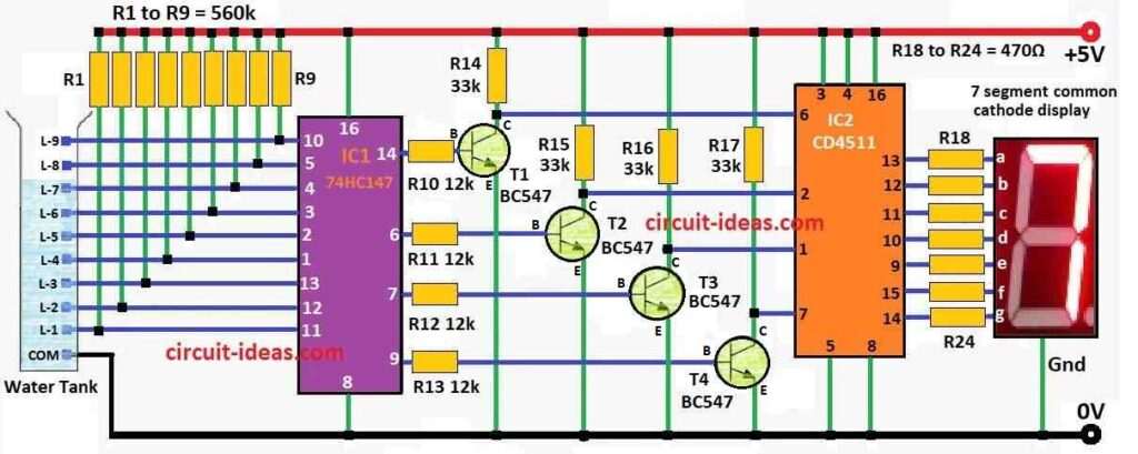
Hence, this number type water level system work on 5V power which uses few main parts like priority encoder IC1 74HC147, BCD to 7 segment decoder IC2 CD4511, 7 segment display LTS543 DIS1, and some other small parts.
When tank is empty all IC1 inputs are high so its output also stay high and because of this all IC2 inputs are low the display then show ‘0’ meaning tank is empty.
As a result, water rises to a level of L1 display show ‘1’ it reaches L8 and it show ‘8’.
When tank is full all IC1 inputs go low and IC1 output become low and IC2 inputs go high then display show ‘9’ meaning tank is full.
Therefore, build this circuit on general PCB and put in box and fix LTS543 on front panel and use stainless steel metal strips for sensor points L1 to L9 and ground so they do not rust in water.
Formulas:
Using ICs like 74HC147 and CD4511 we can make a simple water level indicator that show number on 7 segment display.
Here, is easy guide with some formula and example:
Water Level Sensing:
To check water level use resistors inside tank at different heights and as water goes up it touches more resistors and this change the voltage at each level.
Voltage Divider Formula:
To know voltage at each point use this formula:
Vout = Vin × RL / (RS + RL)
where,
- Vout is the output voltage what sensor reads
- Vin is the input voltage at 5V
- RL is the resistance in water path
- RS is the series in resistor
Above formula help us set correct voltage for each water level, as water rises it gives different voltages.
We can connect these voltages to the ICs 74HC147 + CD4511 which will change the number on the 7 segment display.
Finally, this way we can see the tank level as number 0 to 9 using parts we already have.
How to Build:
To build a Water Level Indicator Circuit with Digital Display follow the below mentioned connections steps:
- First, connect pin 8 of IC1 to ground and pin 16 to positive power.
- For IC2 connect pins 3, 4 and 16 to positive and pins 5 and 8 to ground.
- Now connect sensor wires L1 to L9 to pins 10, 5, 4, 3, 2, 1, 13, 12, 11 of IC1.
- Also, each sensor connects to ground through resistors R1 to R9.
- IC2 connect pins 14, 15, 9, 10, 11, 12, 13 to 7 segment display of LTS543 using resistors R18 to R24.
- After that, connect pins 14, 6, 7, 9 of IC1 to base of transistors T1 to T4 using resistors R10, R11, R12, R13.
Note:
- Build all parts on general purpose PCB and then put everything inside a box.
- Keep the 7 segment display LTS543 on front of the box so we can see it easily and then place the sensor metal strips in the tank at different heights, so how we can measure water level.
Conclusion:
Water Level Indicator Circuit with Digital Display gives easy and clear way to check water level in tank.
Instead of using just LED lights this circuit show number on screen so we come to know exact level of water; also it is more correct and simple to read than old type LED indicators.
Leave a Reply