This Simple 3V to 9V DC Boost Converter Circuit is like a hero for battery.
If battery is only 3V like from old remote then this circuit makes it strong by giving it 9V as many device need 9V to work good.
So if we only have small battery with low power but still want to use the device then this circuit will help a lot.
Circuit Working:
Parts List:
| Category | Component | Quantity |
|---|---|---|
| Capacitors | Electrolytic 470µF 16V 1/4 watt | 1 |
| Semiconductors | IC TL496 | 1 |
| Coil inductor 56µH | 1 | |
| 3V Battery | 1 |
This is DC boost converter circuit works from 3V to 9V and is good when 9V battery is not available or is too costly.
First this circuit is easy type which uses TL496 chip, one coil and one big capacitor.
It gives max 8.6V output which is around 80mA current.
When giving max power it take 405mA from battery.
If there is no load nothing means not connected it only take 125 microamps so battery can last maybe 166 days.
How it work? A simple coil and chip store energy from battery then it sends it output with more voltage and this is done again and again fast.
Feedback part help to keep voltage stable.
Boost converter can be simple or more hard but mostly all have coil, capacitor, chip and feedback part.
How good the circuit works depend on parts and how one will build it.
Formulas:
To get exact values for parts in this circuit we need full information from TL496 datasheet.
But we can give some basic boost converter formulas here:
Duty Cycle (D):
D = (Vout – Vin) / Vout
where:
- D is duty cycle which means how long switch stays ON during one cycle.
- Vout is output voltage and in this circuit it is 9V
- Vin is input voltage with 3V
Inductor Value (L):
L = (Vin * D * ton) / ΔIL
where:
- L is inductor size
- ton is how long switch MOSFET stays ON
- ΔIL is how much inductor current can change the ripple
Note:
These formulas are just to understand how boost converter parts work together.
Actual design is more tricky and for it we needs to do more math like test and maybe simulate to pick exact parts.
How to build:
To build a Simple 3V to 9V DC Boost Converter Circuit follow the below mentioned steps:
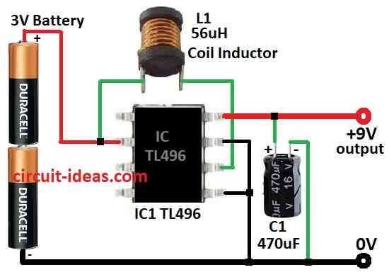
- Connect pin 2 to battery positive side.
- Connect pin 5 and pin 7 to battery negative side.
- Also connect pin 6 to pin 2 and both will connect to battery positive.
- Pin 8 connects to output and this is where we will get 9V output.
- Put one 470µF capacitor from pin 8 to ground the battery negative.
Note:
- This circuit uses small electronic parts and need soldering.
- Be careful while working with electricity and follow safety rules always.
Conclusion:
This Simple 3V to 9V boost converter circuit is very useful part in many electronic stuff and mostly when using battery or low voltage power.
It help to make low voltage go higher so we can use parts that need more power to work right.
In small devices or other things that need more voltage this converter help everything to run good and not stop working.
Leave a Reply