This article for Simple Adjustable Oscillator Circuit using Two Transistors show how to make small sound circuit using only two transistors!
When we turn the knob the sound goes high like beep or low like growl.
We can use four AA battery or small wall power to run this circuit.
Try this easy experiment to learn how electronic makes sound.
What is a Adjustable Oscillator Circuit:
This circuit uses two transistors to make signal go up and down again and again and it is called a adjustable oscillator circuit.
It uses two transistors that work together to help each other.
Main purpose of this circuit is to make sound or signal with steady and changeable frequency.
Circuit Working:
Parts List:
| Category | Description | Quantity |
|---|---|---|
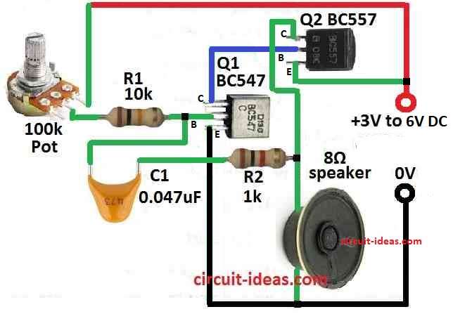
| Resistors | 1k CFR 1/4 W | 1 |
| 10k CFR 1/4 W | 1 | |
| Potentiometer 100k | 1 | |
| Capacitor | Ceramic 0.04µF | 1 |
| Semiconductors | Transistor BC547 | 1 |
| Transistor BC557 | 1 | |
| Speaker 8Ω | 1 |
The power voltage and speaker ohms decide how much current the oscillator uses usually between 10 to 300mA.
Pot P1 makes circuit more useful as it let user change the frequency to many different values.
If we use big potentiometer like up to 1M we can make lowest frequency go down to near 10Hz and this helps to try many kinds of frequencies.
We can also change capacitor C1 between 0.01uF to 0.22uF, this also change how circuit works.
Big C1 value make lower frequency sound.
Because of this circuit can be used for many things like alarm, game, toy or to learn how transistor oscillator work.
Formula:
We can make adjustable oscillator using two transistors by building simple astable multivibrator circuit.
This type of circuit makes square wave again and again and can power speaker with it.
Here is how to build and use main formula:
How to Find Frequency:
For astable multivibrator use this formula:
f = 1.44 / (R1 + 2×R2) × C
where:
- R1 and R2 are resistors at transistor base
- C is the capacitor
How to Build:
Follow the steps below to build a Simple Adjustable Oscillator Circuit using Two Transistors:
- Take all parts we need for circuit like small speaker, transistors, resistors, capacitors and one potentiometer.
- We can use four AA battery or stable 6 volt power to run the circuit.
- Turn potentiometer P1 to make sound go through many different frequency and this will help to test many values.
- Try potentiometer up to 1M to see how frequency changes and it can also make lowest sound go more down.
- Try C1 values from 0.01uF to 0.22uF to see how it changes the sound and this affect how frequency is made.
- Be sure speaker can hear between 100 Hz to 2 kHz sound and this is normal hear range.
- Check how circuit work in toys, alarms or video games also we can use it many way.
Conclusion:
For testing different parts we can change how this Simple Adjustable Oscillator Circuit using Two Transistors work for our own idea.
To ensure circuit always work good check all parts are okay and connection is strong.