This article show how make AM Radio Circuit using Transistors
It use easy parts like transistor, capacitor, resistor and inductor.
Parts are easy to find and good to learn basic radio frequency RF, catch signals and to make sound louder.
Circuit catch medium wave AM signals and changes AM signal to sound and play sound on small 10 ohm speaker.
It is good project for school and people who want to know about radio.
Circuit uses 9V battery to power.
Before making this we need a strong signal place where circuit works best where signal is best.
Circuit Working:
Parts List:
| Component Type | Value / Description | Quantity |
|---|---|---|
| Resistors (All resistors are 1/4 watt unless specified) | 1M, 39k, 6.8k, 2.2k | 1 each |
| Potentiometer 1k | 1 | |
| Capacitors | Trimmer Capacitor 500pF | 1 |
| Ceramic 0.1µF, 470pF | 1 each | |
| Electrolytic 47µF 25V , 4.7µF 25V | 1 each | |
| Semiconductors | Transistors BC547, 2N2222 | 1 each |
| Speaker 10Ω | 1 | |
| Coil: 65 turns of 24SWG enameled copper wire on 100mm long, 10mm diameter ferrite rod; tapping on 5th turn | 1 |
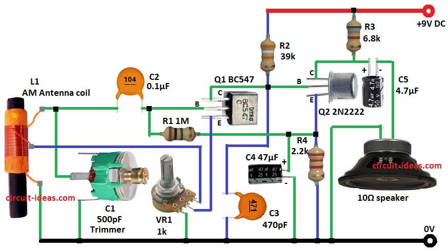
Simple AM radio circuit have few parts to work:
Tuned Circuit and Detector Stage:
- Coil L1 with 60 and 5 turns and plus variable capacitor C1 make tuned LC circuit.
- This choose AM frequency to hear.
- Transistor Q1 work like regenerative detector, which helps for better select signal and for more gain.
- Capacitor C2 send RF signal to Q1 base.
- Potentiometer VR1, resistor R1 and capacitor C3 make bias stable for Q1.
RF Amplifier Stage:
- Detected audio goes to transistor Q2 as Class A amplifier.
- Resistors R2 and R3 set bias.
- Capacitor C4 block DC but let audio pass.
Audio Output Stage:
- Audio from Q2 goes to speaker through capacitor C5.
- Resistor R4 balance load and controls current.
- Speaker 10 ohm make final sound.
Formulas with Calculations:
Here is simple formulas and calculations for AM radio circuit with transistors:
Resonant Frequency of LC Tank:
L1 and C1 pick one AM frequency.
Formula:
f = 1 / (2 × π × √(L × C))
where,
- f is the frequency in Hz
- L is the inductance in H
- C is the capacitance in F
- π is 3.14159
Voltage Gain of Q2 Transistor:
Gain Av for common emitter amplifier:
Av = Rc / Re
where,
- Av is voltage gain for how much signal grow
- Rc is the collector resistor for R3 is 6.8k
- Re is the emitter resistor for R4 is 2.2k
Calculate:
Av = 6.8k / 2.2k = 3.1
This gain is enough to drive small 10Ω speaker.
How to Build:
To build a AM Radio Circuit using Transistors following steps are needed to follow to design our own circuit:
- Put all parts like in circuit diagram show.
- Connect base of Q1 to one side of R2 and other side of R2 go to emitter of Q2.
- Connect C1 from Q1 base to GND.
- Connect C2 between R1 and C1.
- Connect one end of L1 coil to C1 and other end to GND.
- Connect Q1 emitter to center pin of VR1 pot.
- Connect Q1 collector to base of Q2.
- Connect upper pin of VR1 to third wire of L1 coil and lower pin of VR1 goes to GND.
- Connect R1 and C3 in series from positive supply to GND.
- Connect Q2 collector to one end of 10Ω speaker through C5 and other speaker end goes to GND.
- Connect R4 from Q2 emitter to GND.
- Connect positive of C4 from one side of R1 and negative of C4 connect to GND.
- Connect one side of R3 to +9V and other side go to junction of Q2 collector and positive of C5.
Conclusion:
This AM Radio Circuit using Transistors teach how radio works and make signals stronger.
Few parts are needed only to catch and play AM signals.
It is good for school projects and radio hobby.
Circuit is easy to build with no IC needed and is great to learn basics of analog electronics and RF design.