No More Dead Battery! Battery gone down? having no idea? then this Simple Battery Level Indicator Circuit can show battery level.
Also, easy to make, cheap and works fast; furthermore, know when battery is full or low and is good for beginners and DIY lovers.
Circuit Working:
Parts List:
| Components | Values | Quantity |
|---|---|---|
| Resistors | 2.2k 1/4 watt | 1 |
| 680Ω 1/4 watt | 1 | |
| Preset 250Ω | 1 | |
| Semiconductors | Transistor 2N2222 | 2 |
| LED any color 5mm 20mA | 1 |
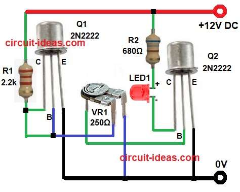
When battery voltage is 12V then Q1 conducts and this keeps base of Q2 biased through preset VR1; then Q2 also conducts and LED1 lights.
If battery voltage drops below set level then Q1 stops conducting and this cuts base current to Q2 and LED1 turns OFF.
So LEDs is ON means battery is good and LED is OFF means low battery.
Formulas:
Below is the formulas for Simple Battery Level Indicator Circuit:
Base Resistor (Rb) Calculation:
We need current to turn the transistor ON.
Formula:
Rb = (Vsource − Vbe) / Ib
where:
- Vsource is the battery voltage
- Vbe is the base-emitter voltage ( 0.7V for 2N2222)
- Ib is the base current
Collector Resistor (Rc) Calculation:
If using resistor with LED:
Formula:
Rc = (Vsource − Vled − Vce) / Ic
where:
- Vled is the LED forward voltage (2V for red LED)
- Vce is 0.2V when transistor is ON
- Ic is the LED current
How to Build:
To build a Simple Battery Level Indicator Circuit follow the connection steps:
- First, assemble all the components as shown in circuit diagram.
- Next, connect transistor Q1 collector to +12V through R1 2.2K., base of Q1 connect to collector of Q2 through VR1 and then emitter of Q1 connect to ground.
- After that, collector of Q2 connect to LED1 and resistor R2 680 ohm, Q2 emitter connect to ground and Q2 base connect to preset VR1 middle pin.
- Now anode of LED1 connect to R2 and cathode of LED1connect to collector of Q2.
- Finally, connect +12V to battery positive and ground to negative of 0V circuit.
Conclusion:
Overall, this Simple Battery Level Indicator Circuit shows battery condition using LED, it uses few cheap parts and works fine for 12V systems.
Also, this project is good for learning transistor switching and voltage sensing and is useful for small solar and battery projects.
Leave a Reply