Want to light up a bulb by using just a battery and switch? then this Simple DC Bulb Circuit is the easiest way to understand how electricity flows and powers small devices.
Also, a perfect starting point for anyone new to electronics.
Circuit Working:
Parts List:
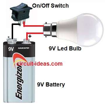
The battery gives DC voltage and the switch controls current flow.
When the switch is ON, current flows from the battery positive to the bulb and then back to the negative terminal.
Then the bulb glows because current passes through its filament and when the switch is OFF then current stops and the bulb goes dark.
Formulas with Calculations:
Formulas for Simple DC Bulb Circuit:
Voltage (V) = Battery voltage
Current (I) = V / R
Power (P) = V × I
If battery = 9V and bulb resistance R = 18 ohms
Then I = 9 / 18 = 0.5A
Power P = 9 × 0.5 = 4.5W
How to Build:
To build a Simple DC Bulb Circuit follow the below steps:
- First, take all the parts as shown in circuit diagram.
- Next, connect the positive terminal of the battery to one side of the switch.
- Then connect the other side of the switch to one terminal of the bulb.
- Now connect the other terminal of the bulb back to the negative terminal of the battery.
Conclusion:
To conclude, this Simple DC Bulb Circuit is very easy to make, as it shows how electric current flows and how a switch controls it; also, it is perfect for beginners and electronics students.
Leave a Reply