Car Reverse Horn with Musical Tone Circuit is easy and fun way to change beep sound to nice tune; its main part is IC UM66 which makes sweet melody.
Also, the 7805 IC reduces the car battery voltage to 5V; additional components support the circuit and help it operate reliably and efficiently.
Furthermore, it is easy to put in car by giving soft sound while reversing and which makes driving better.
Circuit Working:
Parts List:
| Components | Values | Quantity |
|---|---|---|
| Resistors | 100Ω 1/4 watt | 2 |
| Capacitors | Ceramic 0.1μF | 1 |
| Electrolytic 100μ 25V | 1 | |
| Electrolytic 1μF 25V | 1 | |
| Semiconductors | IC 7805 | 1 |
| IC UM66 | 1 | |
| Diodes 1N4007 | 3 | |
| Transistor 2N2222 | 1 | |
| 8Ω Speaker | 1 |
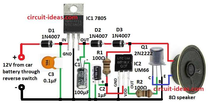
This circuit use car battery 12V for power and IC1 7805 change 12V to 5V steady DC, as 5V is good for IC2 UM66 and other parts.
Then diodes D1, D2, D3 1N4007 keep circuit safe from wrong wire or high voltage.
When IC2 get 5V it plays melody, but melody is weak so it needs more power for speaker., then signal go through 100 ohm resistor R2 to transistor Q1 2N2222.
After that, Q1 make signal strong and act like amplifier and then signal goes to 8 ohm speaker and sound comes out.
Reverse gear switch turns ON the circuit when car goes back.
Further, capacitors C1 and C2 clean power, stop noise and keep stable.
Note: Know the car wires before doing this because wrong connection can harm car system.
Formula:
Formulas and calculations for making this musical horn circuit:
Resistor Calculation:
R1 controls the current flowing to the UM66 and other components, while R2, fixed at 100Ω, which provides sufficient base current to Q1 for amplification.
Formula:
Ib = Ic / hFE
where:
- Ib is the base current
- Ic is the collector current based on speaker power
- hFE is the current gain of transistor 2N2222
How to Build:
To build a Simple Car Reverse Horn with Musical Tone Circuit follow the below mentioned steps for connections:
- First, put all parts like shown in circuit diagram.
- Next, connect capacitor C3 from input of IC1 to GND and connect D1 from input of IC1 to 12V car battery through reverse switch.
- Then connect GND pin of IC1 to GND.
- Also, connect output pin of IC1 to D2 and D3 in series.
- Now connect C1 positive from output of IC1 and C1 negative to GND.
- After that, connect GND pin of IC2 to GND.
- Further, connect VDD pin of IC2 to one side of R1 and other side of R1 between D3 and one end of 8Ω speaker.
- Then connect output pin of IC2 to base of transistor Q1.
- Next, connect C2 positive between R1 and VDD of IC2 and C2 negative to GND.
- Finally, connect collector of Q1 to one side of 8Ω speaker and base of Q1 to output of IC2 and emitter of Q1 to GND.
Conclusion:
To conclude, this Car Reverse Horn with Musical Tone Circuit is simple and cheap project, as it uses UM66 melody IC and few parts to make nice music when car goes back.
Also, it is an good project for car lovers and electronics fans.
Leave a Reply