Think like music conductor who tell each instrument when to play.
In speaker system a Simple Passive Crossover Network Circuit for Loudspeakers do same thing but with sound.
Normal speaker are not made for just one piece but it have many parts each for different sound.
Woofer make big boom sound, tweeter make small squeaky sound and sometimes mid driver make sound in middle.
But crossover works here like smart switch.
It take all music together and then split into parts.
Then tweeter gets high sound, woofer get low sound and mid driver get middle sound.
Circuit Working:
Parts List:
| Type | Description | Quantity |
|---|---|---|
| Resistor | 1.5Ω 7 watt | 1 |
| Capacitor | PPC 3.3uF 100V | 1 |
| Semiconductors | Inductor Coil 0.42 mH | 1 |
| Bass Speaker | 1 | |
| Tweeter Speaker | 1 |
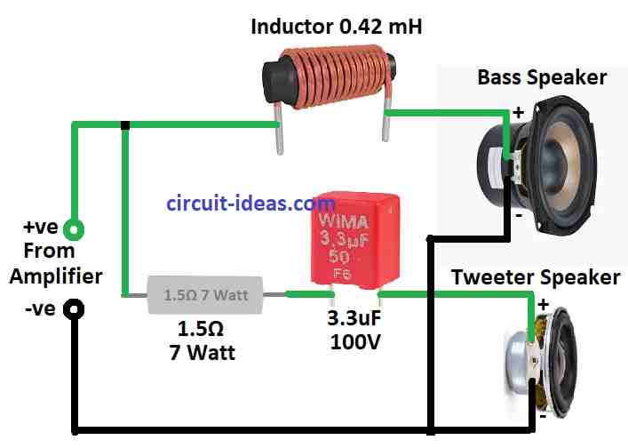
From picture above we can see 3.3uF capacitor and inductor coil are connected to positive input terminal.
Capacitor goes to tweeters negative side and inductor goes to bass speakers positive side.
Negative input wire goes straight to both speakers negative side.
There is optional for 2.2 ohm 7 watt resistor.
We can use it if we want to make tweeter sound little louder.
If we take out 1.5 ohm resistor and put 2.2 ohm then we can get about 0.8 dB more loudness.
This basic crossover, cut sound by 6 dB per octave and works around 4 kHz.
Tweeter side has resistor and capacitor.
Woofer side has coil inductor choke to help control bass and mid sounds.
Capacitor keep tweeter safe and resistor make tweeter little less loud by 1.4 dB so both speakers match better.
Crossover uses good quality air core coils and polyester capacitors for better sound.
Using few parts help system work better for long time and simple crossover is good for this.
Final system has 88.6 dB SPL at 1 meter with 1 watt which is better than older low power systems.
Formula:
This formula below uses for low sound filter in passive crossover circuit:
C = 1 / (2 π f Xc)
where:
- C is capacitor value for capacitance in farads F.
- π (pi) is math number about 3.14159.
- f is signal frequency in hertz Hz.
- Xc is capacitive reactance in ohms Ω.
This formula tell how to find Xc using frequency and capacitor value.
Note:
This formula help to understand how capacitor work in AC signal.
If we know capacitor size and frequency we can know how much it will stop or slow down current we can call this reactance like resistance for AC.
How to Build:
To build a Simple Passive Crossover Network Circuit for Loudspeakers follow the below mentioned steps for connections:
- First look at the circuit diagram and try to understand it.
- Find the input coil (inductor), capacitor, bass speaker and tweeters positive and negative wires.
- Like in the diagram connect the positive wire from input to both capacitor and coil.
- Join the coil to bass speakers positive side.
- Be sure both bass and tweeters negative wires go to negative input line.
- Connect tweeters negative side to the capacitor.
- This setup makes a crossover point between tweeter and bass speaker.
- Use solder to make connections strong.
- Wires must be clean and covered well to stop short circuit.
Testing the circuit:
- After building crossover test with speaker and music source.
- Check if all parts are working and sounds goes to right speaker.
Adjusting if Needed:
- We can change resistor or crossover parts if the sound does not feel right or if our speakers are different.
Conclusion:
This Simple Passive Crossover Network Circuit for Loudspeakers helps each speaker play only what it should with less distortion and better sound.
Crossover can be simple or hard based on how many speakers and how good sound we want.