Simple Hartley Oscillator Circuit is like small sound maker with electric, as it makes smooth sound like whistle and does not stops.
Also, it uses coil with center tap like two coil join and one capacitor help keep sound going.
Need one active part to make sound strong, as this sound circuit is different from others.
Circuit Working:
Parts List:
| Components | Values | Quantity |
|---|---|---|
| Resistors | 390k 1/4 watt | 1 |
| 1k 1/4 watt | 1 | |
| Capacitors | Ceramic 0.1µF | 1 |
| Ceramic 0.02µF | 1 | |
| Electrolytic 100µF 25V | 1 | |
| Semiconductors | Transistor 2N2222 | 1 |
| ON/OFF switch | 1 | |
| Transformer (see text) | 1 |
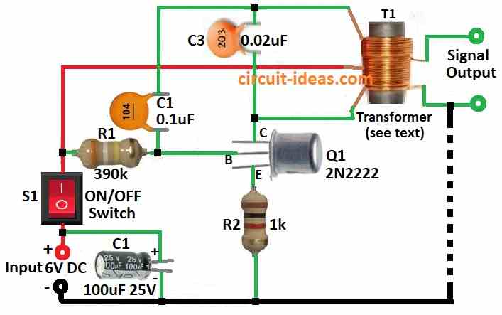
This is Hartley oscillator circuit uses center tap coil for tuning and feedback where as other coil gives output.
Hence, to make it we need small transformer T1 of 500 ohm to 30 ohm with center tap, with primary side is 500 ohm and secondary is 30 ohm around.
Also, top part of coil L1 goes to transistor base and bottom part goes to collector.
Capacitor C3 help set frequency and this frequency depend on C3 and coil, if C3 is 0.02µF then frequency is about 2 kHz, so to get more frequency use smaller C3 and to get less frequency use bigger C3.
Furthermore, C2 is not for tuning but is is just to stop DC going from collector to base.
Output is 0.8V RMS when there is no load and it uses 2 mA current with 6V battery.
Formulas:
Hartley Oscillator Frequency Formula:
Hartley oscillator make sound at certain frequency (f) and we can find this frequency using this formula:
f = 1 / (2 * π * √(Leq * C))
where:
- f is frequency in Hertz Hz.
- Leq is total inductance in Henrys H.
- C is capacitor value in Farads F.
How to Find Leq (Equivalent Inductance):
In the circuit, transformer T1 behaves like an inductor and its total inductance is called Leq and also we can calculate Leq as follows:
Leq = T1 + 2M
where:
- M is mutual inductance between two coils in transformer.
Note:
To simplify the math, we sometimes ignore (M) in actual circuits when the coils are not strongly coupled.
Like Colpitts, Hartley frequency can also change little because of small hidden capacitance, part mistake or how transistor works.
How to Build:
To build a Simple Hartley Oscillator circuit we need to follow the below steps:
- First, connect collector of transistor Q1 to one side of transformer primary coil.
- Next, connect emitter of Q1 to ground using resistor R2 and connect base of Q1 to resistor R1 and then connect R1 to positive supply from switch S1.
- After that, put capacitor C2 between base of Q1 and resistor R1.
- Now connect capacitor C3 across in parallel with primary coil of transformer and this is for tuning frequency.
- Then connect capacitor C1 from DC power input to ground for filtering.
Note:
- Use 6V DC power supply to power the circuit and it should start working means oscillating and give out sine wave AF at the set frequency.
- Also, change value of C3 to adjust means fine tune the frequency.
Conclusion:
To conclude, Simple Hartley Oscillator Circuit make high-frequency sine wave and it uses tapped coil or transformer for tuning and feedback.
Hence, this circuit is good for RF or any device that need steady wave.
Leave a Reply