Simple IC TDA2822 Stereo Audio Amplifier Circuit is small chip with stereo amplifier makes weak music sound go louder which is strong enough for speaker or headphone.
Despite using very little energy it still provides 250 milliwatts each side with good sound for small things like walkman, hearing aid or little stereo.
So next time anyone hears music should say thanks to TDA2822 for making it loud and nice.
Circuit Working:
Parts List:
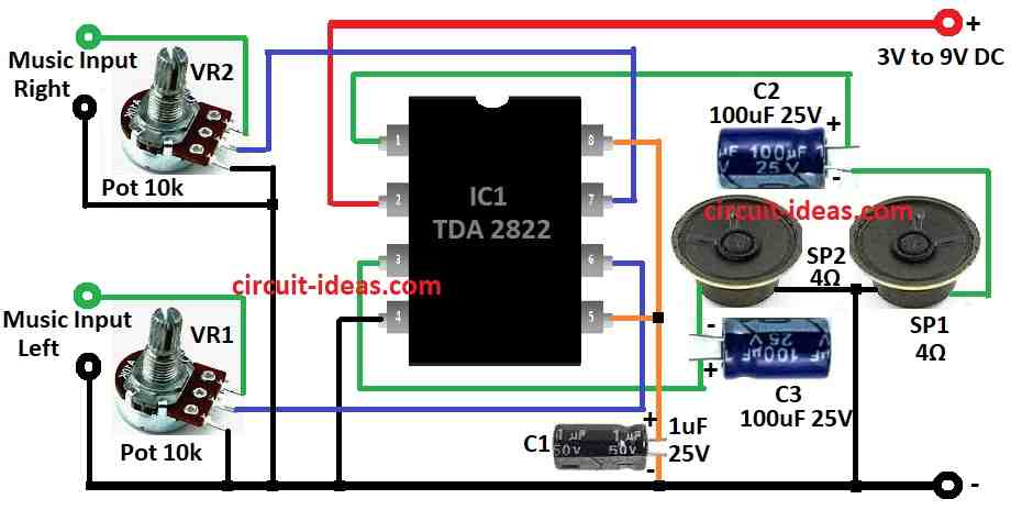
| Component | Specification | Quantity |
|---|---|---|
| Potentiometer | 10k | 2 |
| Capacitors | ||
| Electrolytic | 100µF 25V | 2 |
| Electrolytic | 1µF 25V | 1 |
| Semiconductors | ||
| IC | TDA2822 | 1 |
| Speakers | 4Ω, 2.5 inch diameter | 2 |
TDA2822 is stereo amp chip it does not use much power, but is good for walkman and hearing aid.
It gives 250mW sound power which is so nice for small power stuff.
Also it can be used before big stereo amp like preamp.
The Chip has got two input and two output which gives 250 milliwatt sound.
This amp circuit is made to work quiet with no noise.
One can connect speaker straight to output with capacitors.
Formulas:
TDA2822 is small stereo amp chip.
Many people use it in low power audio projects.
It got two amps inside works good with low voltage like in portable music players.
It gives decent power around 1 watt for each side which is so good for small speakers and battery stuff.
If anyone want to build stereo amp with TDA2822 here are some important things to know:
Power Output Formula:
One can find power (Pout) for each channel like this:
Pout = VCC² / 8RL
where:
- VCC is voltage one can give to chip
- RL is speakers in ohm for impedance
Gain Formula:
TDA2822 already have fixed gain inside.
But we can control sound loudness with potentiometer.
This formula show how output and input relate:
Vout / Vin = R1 / (R1 + R2)
where,
- R1 and R2 are parts of the pot where we can use it to change the input level
Choosing Capacitor:
Capacitors connect audio signal and block DC.
To know how strong capacitor reactance works use this formula:
XC = 1 / (2πfC)
where:
- f is sound frequency like 20 Hz to 20 kHz
- C is capacitor value
Pick capacitor big enough so it does not block audio sound in the range.
Note:
With these formulas we can make stereo amp using TDA2822.
Just change values based on what parts one is having and what one want it to do.
Make small changes, test and enjoy ones music project.
How to Build:
To build a Simple IC TDA2822 Stereo Audio Amplifier Circuit we need to follow the below mentioned steps:
- Connect VCC pin to plus side of power.
- Connect GND pin to minus ground side.
Audio Input:
- Put the sound input like from phone or laptop to VR1 and VR2 pins.
Speaker Output:
- Connect speaker to pin 1 and pin 3 using 100µF 25V capacitor in series.
- Use decoupling capacitor for better sound and with less noise.
Extra Parts:
- One may need more capacitators or resistors for filter, bias or better working.
- Check TDA2822 datasheet for best values.
- After building the circuit test it with audio.
- Turn volume knob if having one
- Be sure sound coming out good.
Important:
- Be safe when working the electronics.
- Always connect power with right polarity.
- Use right voltage so the parts do not break.
Conclusion:
This Simple IC TDA2822 Stereo Audio Amplifier Circuit is good for hobby people, cheap, easy and work with battery.
TDA2822 is small stereo amp chip which makes one music sound louder.
We can think like small volume booster for speaker or headphone.