This project for Simple LED Flashing Circuit with Arduino Uno is simple guide for learn electronics and Arduino.
We can learn connect parts and use code to blink LED.
It look easy but help us learn big and understand hard projects later.
Coding:
int ledPin = 13; // Select the pin to which the LED is connected

void setup() {
  pinMode(ledPin, OUTPUT); // Declare the LED pin as output
}

void loop() {
  digitalWrite(ledPin, HIGH); // Turn the LED on
  delay(1000); // Wait for one second
  digitalWrite(ledPin, LOW); // Turn the LED off
  delay(1000); // Wait for one second

}
Code Explanation:
- int led Pin 13 makes one variable name ledPin which gives value 13 with Arduino digital pin 13.
- pinMode(ledPin, OUTPUT) says pin 13 is output, so Arduino can send power.
- digitalWrite(ledPin, HIGH) gives power of 5V to pin and LED turns ON.
- delay(1000) wait 1000 milliseconds in 1 second.
- digitalWrite(ledPin, LOW) stops power 0V and LED turns OFF.
- delay(1000) wait again for 1 second.
- All these steps repeat again and again in loop() so LED blink again and again.
Circuit Working:
Parts List:
| Component | Quantity |
|---|---|
| Resistor | |
| 220Ω 1/4 watt | 1 |
| Semiconductors | |
| Arduino Uno board | 1 |
| Any LED 5mm 20mA | 1 |
| IC 7809 | 1 |
In this easy Arduino project we learn how to blink LED turn ON and OFF again and again.
LED blinking means LED goes ON and then OFF again and again which is very common in electronics and microcontroller projects.
LED is small light part and it gives light when current goes through it.
But LED does not like too much current as too much can break it.
So we have to use resistor to stop too much current and this help keep LED safe.
Arduino pin can be HIGH or LOW.
HIGH means about 5V power.
With resistor and voltage current flows and LED turns ON.
When pin is LOW there is no power with current stops and LED turns OFF.
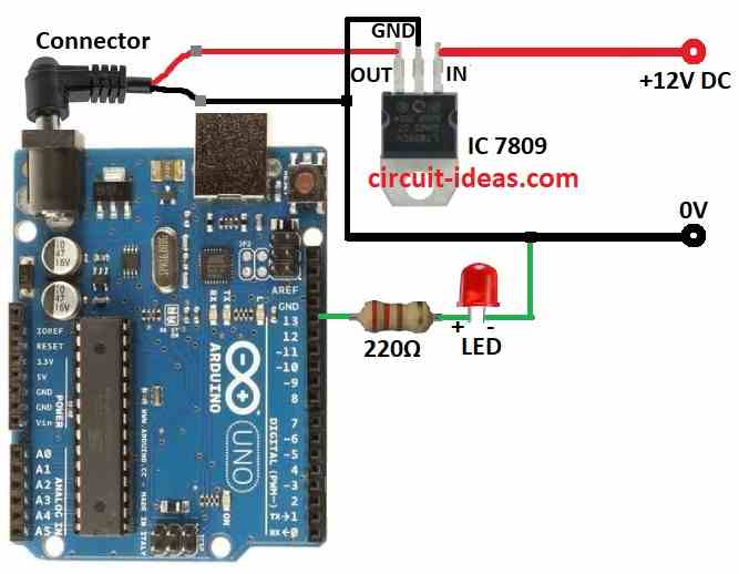
How to Build:
To build a Simple LED Flashing Circuit with Arduino Uno follow the below mentioned steps connections steps:
- Take all parts as shown in circuit diagram.
- Use IC 7809 to give steady 9V power to Arduino.
- Connect LED short leg cathode to Arduino GND.
- Connect long leg anode of LED to one side of 220Ω resistor.
- Connect other side of resistor to Arduino pin 13 of digital output.
Note:
- 220Ω resistor is important as it saves LED from too much current.
- Wrong resistor can damage the LED.
- Always put LED correct way like long leg anode is positive.
- Arduino has many digital pins and we can use others too if needed.
Conclusion:
We can make Simple LED Flashing Circuit with Arduino Uno which can be our first step in electronics and coding.
This project shows how hardware and software work together.
Now we can try bigger things like sensors, motors and cool light patterns!
Leave a Reply