This project presents a simple transistor based bicycle tail light flashing circuit; the circuit primarily functions as a bicycle tail light and operates from a low voltage battery, making it suitable for portable use.
Moreover, the circuit uses very few components, because of this its easy to build and also, power consumption is low and therefore the battery life is good.
Circuit Working:
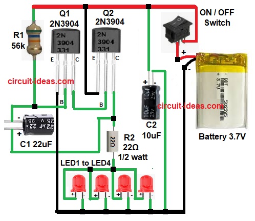
Parts List:
| Components | Values | Quantity |
|---|---|---|
| Resistors | 56k, 22Ω 1/2 watt | 1 each |
| Capacitors | Electrolytic 22uF 25V, 10uF 25V | 1 each |
| Semiconductors | Transistors 2N3904 NPN | 2 |
| Red LED | 4 | |
| ON / OFF Switch | 1 | |
| Battery 3.7V | 1 |
To begin with, the 3.7 V power supply powers the circuit; when switch S1 turns ON, it applies power to the circuit.
Initially, capacitor C1 starts charging, so base of transistor Q1 gets voltage slowly and because of this Q1 turns ON after some time and then Q2 also turns ON.
Now current flows through resistor R2, as a result LEDs start glowing and after that the capacitor C1 discharges, so Q1 turns OFF again.
Then, transistor Q2 also turns OFF, which switches the LEDs OFF; the circuit repeats this process continuously, causing the LEDs to blink and create a flashing effect.
Formula with Calculation:
Battery voltage = 3.7V
Assume LED forward voltage = 2V
Number of LEDs in parallel = 4
Voltage across resistor R2 =
V = Battery voltage – LED voltage
V = 3.7 – 2 , V = 1.7V
Assume LED current = 20mA per LED
Total LED current = 20mA x 4
Total current = 80mA or 0.08A
So resistor value =
R = V / I
R = 1.7 / 0.08, R = 21.25 ohm
So the nearest standard value used in this circuit is 22 ohm 1/2 watt
How to Build:
To build a Transistor Based Bicycle Tail Light Flashing Circuit follow below steps for connections:
- First, take all the parts as per circuit diagram.
- Next, connect emitter of Q1 to cathode of LED1 to LED4.
- Then connect base of Q1 between resistor R1 and negative of capacitor C1.
- After that, connect collector of Q1 to base of Q2.
- Now connect emitter of Q2 to positive supply, connect base of Q2 from collector of Q1 and connect collector of Q2 between one end of resistor R2 and positive of capacitor C1, and afterwards connect other end of resistor R2 to LED anode lines.
- Also, connect capacitor C2 positive to battery positive and connect capacitor C2 negative to battery negative.
- Finally, connect battery positive to switch S1 and connect battery negative to circuit ground.
Conclusion:
Overall, this Transistor Based Bicycle Tail Light Flashing Circuit is simple and useful, as it uses low cost components and it works on low voltage; as a result, because of transistor switching the blinking is stable.
Therefore, this circuit is good for bicycle safety light and also beginners can build this easily.

Leave a Reply