Building a transistor-based LED chasing flashing circuit is a simple and interesting project, as this circuit switches LEDs ON and OFF sequentially to create a chasing effect, which gives it the name “chaser circuit
This circuit uses simple transistors instead of ICs, making it easy for beginners to learn, it is suitable for learning and decorative applications, and its low-cost, readily available components make it economical to build.
Circuit Working:
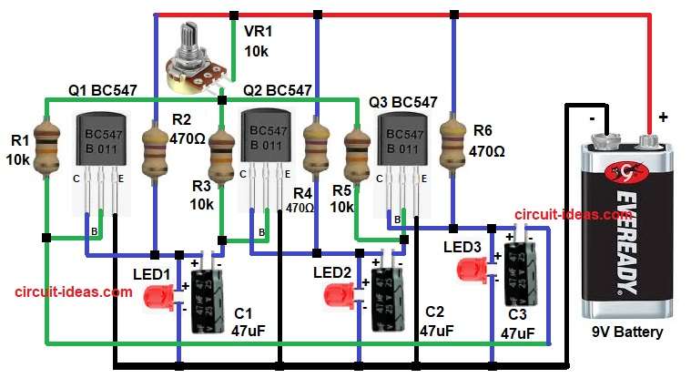
Parts List:
| Components | Values | Quantity |
|---|---|---|
| Resistors (All resistors are 1/4 watt) | 10k | 3 |
| 470Ω | 3 | |
| Potentiometer 10k | 1 | |
| Capacitors | Electrolytic 47uF 25V | 3 |
| Semiconductors | Transistors BC547 NPN | 3 |
| LEDs any color | 3 | |
| Battery 9V | 1 |
When the circuit receives power, capacitor C1 starts charging through resistor R3; at the same time, transistor Q1 turns ON, causing LED1 to glow.
After some time C1 becomes fully charged and then the voltage at base of Q2 changes, so transistor Q2 turns ON and LED2 glows and at the same time Q1 turns OFF.
Next, capacitor C2 starts charging through resistor R5 and after a short delay transistor Q3 turns ON and LED3 glows and then at the same time LED2 turns OFF.
Now capacitor C3 discharges and gives signal back to Q1 and therefore, this process repeats again and hence, the LEDs glow one by one continuously.
Formulas with Calculation:
- Formula for base resistor calculation:
Rb = (Vcc – Vbe) / Ib
Assume:
- Vcc is 9V
- Vbe is 0.7V
- Ib is 0.8mA
Rb = (9 – 0.7) / 0.0008
Rb = 8.3 / 0.0008
Rb = 10375 ohm
So 10k resistors used.
2. LED current limiting resistor:
Rled = (Vcc – Vled) / Iled
Assume:
- Vled is 2V
- Iled is 15mA
Rled = (9 – 2) / 0.015
Rled = 7 / 0.015
Rled = 466 ohm
So 470 ohm resistors used.
How to Build:
To build a Transistor Based LED Chasing Flashing Circuit follow below steps for connection:
- First, assemble all the parts as shown in the circuit diagram.
- Now transistor Q1 emitter goes to 9V battery negative, then collector goes to LED1, R2 and C1 anode and base goes to R1 and capacitor C3 cathode.
- After that transistor Q2 emitter goes to 9V battery negative, then collector goes to LED2, R4 and C2 anode and base goes to R3, VR1 and capacitor C1 cathode.
- Similarly transistor Q3 emitter goes to 9V battery negative, then collector goes to LED3, R6 and C3 anode and base goes to R5 and capacitor C2 cathode.
- Finally, the battery positive goes to one end of resistor R1, VR1, R4 and R6.
Conclusion:
To conclude, this Transistor Based LED Chasing Flashing Circuit is very useful for beginners, it helps to understand transistor switching and RC timing clearly.
Also, the circuit uses no IC, which keeps the design simple and easy to build and test; we can add more LED stages if needed, further, making the circuit is suitable for learning and decorative applications.

Leave a Reply