This circuit uses a PIR sensor to detect human motion.
When motion happens, PIR output goes high.
This high signal turns ON an LED through a resistor.
Simple PIR Motion Detector Circuit is easy to make and works with 12V supply.
Circuit Working:
Parts List:
| Part Name | Value | Quantity |
|---|---|---|
| Resistors | 220Ω 1/4 watt | 1 |
| Semiconductors | PIR Sensor HC SR501 | 1 |
| LED any 5mm 20mA | 1 | |
| Battery 5V to 9V | 1 |
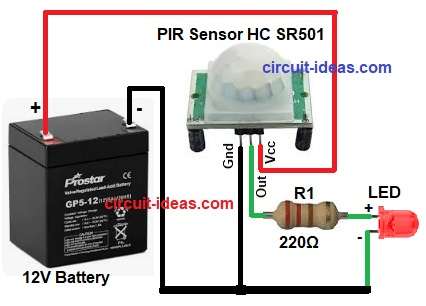
PIR sensor has three pins: Vcc, Out and Gnd.
Vcc pin goes to positive of battery.
Gnd pin goes to negative of battery.
Output pin gives low voltage when no motion.
Output pin gives high voltage when motion detected.
LED is connected to battery through PIR output and one R1 resistor.
When PIR output is low then LED is OFF.
When PIR output becomes high then current flows through resistor and LED turns ON.
Formulas with Calculation:
Below is the formulas for Simple PIR Motion Detector Circuit:
LED current formula: I = V / R
Suppose PIR output high = 12V
LED forward drop = 2V
Voltage across resistor = 12 – 2 = 10V
R = 220Ω
So LED current I = 10 / 220 = 0.045A
LED current is around 45mA.
This is safe for common high brightness LED.
How to Build:
To build a Simple PIR Motion Detector Circuit follow the below steps for connections:
- Take all the parts as shown in circuit diagram.
- PIR Vcc pin connect to battery positive 12V.
- PIR Gnd pin connect to battery negative.
- PIR output pin connect to one end of R1 resistor.
- Other end of resistor R1 connect to LED anode (positive side).
- LED cathode (negative side) connect to battery negative.
Conclusion:
This is project is for Simple PIR Motion Detector Circuit with one PIR sensor, one resistor and one LED.
PIR senses human movement and turns LED ON automatically.
Circuit is cheap, easy and useful for small security or automatic light applications.