
This article for Simple RF Sensor without Battery Circuit show how to make small tester with no battery, also it help to check if radio transmitter is working or not.
Moreover, the tester receives power from radio waves sent by the transmitter and if the transmitter works properly, the LED light blinks to indicate it.
What is a RF Sensor without Battery:
An RF sensor with no battery is a wireless sensor that can detect radio signals without using a normal battery or other power source.
Instead, the sensor takes a small amount of power from nearby radio signals, a process called energy harvesting.
Also, this kind of sensor are good for many uses like internet of things, factory work and checking environment.
Circuit Working:
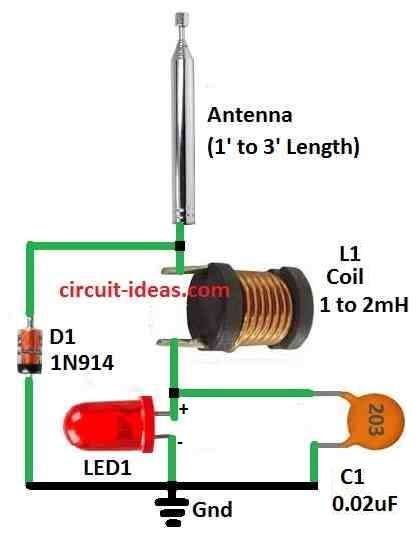
Parts List:
| Components | Values | Quantity |
|---|---|---|
| Capacitors | Ceramic 0.02µF | 1 |
| Semiconductors | Diode 1N914 | 1 |
| Bright LED (any type) | 1 | |
| Antenna (as given in diagram) | 1 | |
| Coil (as given in diagram) | 1 |
This is how RF sensor circuit with no battery works:
The circuit uses antenna to catch RF signal and antenna can be simple wire or small stick antenna.
When RF transmitter is ON it sends out radio signals and the antenna catches these radio waves, also these radio waves make small voltage in the antenna wire.
Furthermore, mostly one germanium diode take this voltage and changes AC signal which is radio wave into DC signal of normal power.
This conversion from AC to DC called rectification, produces useful DC power from the radio signal.
Then this power goes to capacitor and this capacitor is small part that keep power for short time.
After that, the capacitor supplies power to turn ON the LED light, shown as LED1 in the circuit diagram.
When power in capacitor is enough to reach certain voltages then the LED1 light turn ON; also LED should be high brightness type because RF power is very small because the normal LED may not work good.
However, to test if RF transmitter is working we bring sensor antenna close to transmitter antenna and this gives strong signal to sensor.
Hence, when an RF signal arrives the sensor generates enough voltage to charge the capacitor and light LED1 and when LED1 turns ON, it indicates that the circuit has detected a working RF signal.
Formula:
Formulas for Simple RF Sensor without Battery:
Main Idea: Diode Rectification:
This circuit work like simple rectifier using diode and diode let current goes in one way but stop it going back other way.
We can understand diode working with this formula:
Id = Is × (exp(Vd / (n × kB × T)) – 1)
where:
- Id is current going through diode
- Is is small leakage current called saturation current
- Vd is voltage across diode
- n is ideality factor of diode value between 1 and 2
- kB is Boltzmann constant
- T is temperature in Kelvin
How circuit work:
Diode D1 takes weak AC voltage from the antenna and converts it into DC and when the AC signal goes positive, the diode lets current pass and charges capacitor C1
When AC connects negative, then diode stop current with no flow.
Then capacitor C1 keep this charge and help make DC more stable with less ripple for using in next parts of the circuit.
Note:
This formula show how voltage and current behave in diode, also we do not use it directly for this simple circuit but it help to understand how diode work.
How to Build:
To build a Simple RF Sensor without Battery Circuit follow the below mentioned connection steps:
Choosing LED:
- First, use high brightness LED so it can light up well using small power from RF signal.
Tuning the Antenna:
- Then we can use old pull up antenna from TV or CB radio or just use simple wire and this wire will work as antenna for the circuit.
Housing for Circuit:
- After that, put all parts in small plastic or metal box and box should protect the parts and keep them in place.
Connecting the Circuit:
- Next, connect the LED1 to the circuit; the circuit turns on LED1 when it detects an RF signal.
- Also, this circuit is special because it needs no battery or outside power.
How to Test:
- Turn ON CB radio or ham radio which we want to test and then put the circuits antenna close or touching the transmitter antenna.
- Watch LED1, if LED1 turns ON it means RF signal is coming and circuit is working.
Conclusion:
To conclude, this small and Simple RF Sensor circuit can test RF transmitters with no battery; as it uses RF signal energy to light the LED.
Also, it is very good idea for hobby people or beginners who want easy RF project.