Signal Injector Circuit is small tool for electronics.
It send special signal inside the circuit.
This help to find problem or see where signal goes.
Mostly it is used in sound and radio circuit but can use in other circuit also.
Circuit Working:
Parts List:
| Category | Item | Quantity |
|---|---|---|
| Resistors | 100k 1/4 watt | 2 |
| 10k 1/4 watt | 2 | |
| Capacitors | Ceramic 0.01µF | 3 |
| Semiconductors | Transistors BC547 | 2 |
| Battery 1.5V | 1 | |
| Probe | 1 | |
| Crocodile Clip | 1 |
Signal injector circuit is very useful tool to fix circuit problem fast.
We can use it on speaker output like in radio to find bad part.
If we hear the sound at output then go back to check stage before like an audio amplifier.
Keep moving injector step by step to each part and listen for a signal.
This way we can find where problem is.
Formula and Calculations:
This circuit have two NPN transistors connect in cross way and two RC timing parts.
It changes between two states one transistor is ON other one is OFF.
This type of circuit is called BJT astable multivibrator.
It make signal that goes ON and OFF again and again.
We can find how fast it switches which is called frequency by this formula:
f = 1 / (1.4 * R * C)
where:
- f is frequency in hertz Hz
- R is resistor value in ohms Ω
- C is capacitor value in farads F
Assume both resistors and capacitors are same value
Important:
This formula give just near result.
Real value maybe little different because of transistor and other parts.
If want better result use circuit simulator or more advanced formula that include transistor details.
When both RC parts are same output signal have about 50% duty cycle which is ON and OFF same time.
Example:
If resistor is 10k ohm and capacitor is 0.01µF then:
f = 1 / (1.4 * 10000 * 0.00000001) = 7142.86 Hz almost 7.14 kHz
Note:
This formula work for ideal parts.
In actual circuit we may need to test and adjust to get right signal.
By understanding how formula and circuit work we can build signal injector that fits our testing need.
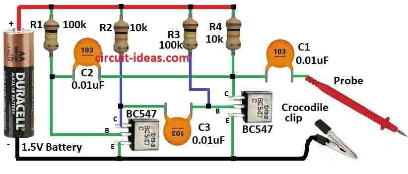
How to Build:
To build a Signal Injector Circuit we need to follow the below mentioned connection steps:
Assembling Steps:
- Connect base of first BC547 transistor to R1 resistor and connect its collector to R2 resistor and Emitter to ground.
- Take second BC547 transistor and connect its base to C3 capacitor and collector connect to R4 resistor and emitter to ground.
- Join capacitor C1 and C2 in series, one side connect to R1 resistor and other side to probe.
- Fix crocodile clip to negative side of power supply.
- One leg of capacitor C3 connects to collector of first BC547 and other leg connect to base of second BC547 transistor.
Safety Precautions:
- Use good insulation and cover to stop electric shock.
- Do not use high voltage or big current it can break the circuit.
Note:
- This simple signal injector help to send audio signal into circuit for testing and fixing.
- We can change frequency for different circuit need.
Conclusion:
Signal injector circuit is useful tool for testing and fixing electronic circuit.
It put known signal inside the circuit so we can find problem and follow signal path.
It is very helpful circuit for people who work with electronics both beginners and experts.