LM4910 IC is special chip.
It makes stereo headphone sound good by using a very low power.
The circuit is useful for small devices like MP3, phone, battery gadgets.
It work on low voltage to around 3.3V and has shutdown mode to save power.
This article for Simple Stereo Headphone Amplifier Circuit using IC LM4910 shows how to design, build and understand stereo amp with IC LM4910.
Circuit Working:
Parts List:
| Component | Specification | Quantity |
|---|---|---|
| Resistors | 20k 1/4 watt | 4 |
| Capacitors | PPC 0.39µF | 2 |
| Electrolytic1µF | 1 | |
| Semiconductors | IC LM4910 | 1 |
| Stereo Headphone | 1 |
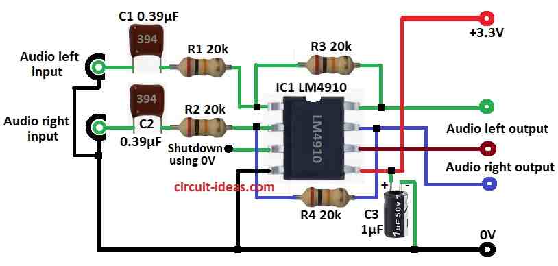
Circuit uses 3.3V DC power.
Audio come from left and right input and goes through capacitors C1 and C2 into LM4910 chip.
C1 and C2 blocks DC and only lets AC audio signal pass to amp.
Gain sets by resistors R1, R2, R3, R4 which are all 20k and give a balanced gain.
LM4910 boost signal and send to left and right headphone out.
Audio is clear and with low distortion.
Capacitor C3 connects to pin 5 bypass, reduces power noise and keep output clean.
Pin 3 is shutdown pin which connects to ground to turn OFF the amp and save power.
Formulas with Calculations:
Here are formulas and calculations for Simple Stereo Headphone Amplifier Circuit:
Formula for Gain:
Gain = R3 / R1 = R4 / R2
All resistors are 20k so:
Gain = 20k / 20k = 1 (unity gain)
Cutoff Frequency:
Formula:
fc = 1 / (2 × π × Rin × Cin)
where:
Rin is 20k
Cin is 0.39μF
fc = 1 / (2 × 3.14 × 20000 × 0.39×10⁻⁶)
fc = 20.4 Hz
So low signals below 20.4 Hz are blocked.
How to Build:
To build a Simple Stereo Headphone Amplifier Circuit using IC LM4910 following steps should be followed for assembling and connections:
- Collect all parts from circuit diagram.
- Connect left audio input to pin 1 of LM4910 through capacitor C1.
- Put resistor R1 between pin 1 and pin 8.
- Connect right audio input to pin 2 through capacitor C2.
- Place resistor R2 between pin 2 and pin 7.
- Use switch or jumper at pin 3 for shutdown and to turn OFF the amp and connect pin 3 to ground.
- Connect pin 4 to GND.
- Connect capacitor C3 from pin 5 to GND which reduces noise and keep output stable.
- Connect left headphone output to pin 6.
- Put resistor R3 between pin 8 and pin 1.
- Connect right headphone output to pin 7.
- Place resistor R4 between pin 2 and pin 7.
- Give 3.3V power to pin 5.
Conclusion:
This project for Simple Stereo Headphone Amplifier Circuit using IC LM4910 is small, easy and works well.
It uses low power, need few parts and give clear sound.
Its good for hobby and for professional audio work.
We can change design for different sound as per our needs.
Leave a Reply