
Many people think a buzzer is necessary to produce sound, but this circuit proves otherwise by generating sound with only a few components.
This Simple Transistor Oscillator Speaker Circuit does not use a buzzer, instead, the transistors drive a small speaker directly, allowing the circuit to generate sound on its own.
Moreover, it is very easy to build as a result the beginners can learn transistor working clearly.
Circuit Working:
Parts List:
| Components | Values | Quantity |
|---|---|---|
| Resistors | 47k,1.2k ,120Ω | 1 each |
| Capacitors | Electrolytic 33µF 25V | 1 |
| Ceramic 0.047µF | 1 | |
| Semiconductors | Transistor BC547 NPN | 1 |
| Transistor BC557 PNP | 1 | |
| LED any color | 1 | |
| Speaker 8Ω or Small Speaker | 1 | |
| Power Supply 9V Battery | 1 |
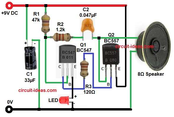
First, we apply the 9V power supply to the circuit, then capacitor C1 starts charging through R1, causing transistor Q1 to turn ON gradually and as a result, current flows through LED1.
Next, capacitor C2 provides feedback to transistor Q2, causing it to switch ON and OFF rapidly, also this switching produces oscillations, which make the speaker vibrate and generate a buzzing sound.
Also, both transistors work together as a switching amplifier and thus the sound generation becomes stable.
Formulas with Calculation:
- The formula for charging time of capacitor C1
Time constant = R1 x C1
R1 is 47,000k
C1 is 33 microfarad
Time constant = 47000 x 33 x 10^-6
Time constant = 1.55 seconds
Therefore, this delay helps in oscillation start.
2. Base current calculation for Q1:
Assume base voltage = 0.7V
R2 = 1.2k
Base current = 0.7 / 1200
Base current = 0.00058 amp
Base current = 0.58 mA
Hence, this current is enough to drive the transistor.
How to Build:
To build a Simple Transistor Oscillator Speaker Circuit follow the below connection steps
- So first we need to gather all the circuit parts.
- Next, the emitter of transistor Q1 connects to ground through an LED, the base connects to resistors R1 and R2, and the collector connects to the base of Q2 through resistor R3.
- Now, transistor Q2 emitter pin connect to Vcc 9V.
- Meanwhile its base pin connect with R3 and also collector of Q1 and then then collector pin connects to one end of capacitor C2 and one end of speaker.
- Finally, capacitor C1 positive terminal goes to Vcc 9V and negative terminal goes to GND.
Conclusion:
To conclude, this Simple Transistor Oscillator Speaker Circuit is easy to build, here, the circuit uses few components and is good for students and beginners.
Furthermore, it helps to understand transistor oscillation and therefore this circuit is ideal for basic electronics projects.