Smart Headlight Automation Circuit using IC 555 turns ON the car light by itself when dark.
It uses LDR to check light outside and 555 IC decide when light turns ON.
This circuit saves power, make car light work at right time and help driver be safe at night.
Circuit Working:
Parts List:
| Component | Quantity |
|---|---|
| Resistors | |
| 4.7k 1/4 watt | 1 |
| LDR | 1 |
| Preset 100k | 1 |
| Capacitors | |
| Ceramic 0.01µF | 1 |
| Electrolytic 10µF 25V | 1 |
| Semiconductors | |
| IC 555 | 1 |
| Transistor BC547 | 1 |
| Relay | 1 |
| Diode D1 1N4007 | 1 |
| On / Off switch | 1 |
| Battery 12V | 1 |
In this circuit LDR and VR1 make voltage divider.
Light changes voltage at point between LDR and VR1.
More light means LDR low resistance with low voltage to 555 IC.
Less light means LDR high resistance with voltage to 555 IC goes up.
555 IC checks if voltage passes the limit.
If yes then output from 555 IC goes high.
High output turns ON the transistor Q1 BC547 through which the current flows in relay coil.
Relay closes N/O contact with headlights turns ON.
Diode D1 1N4007 protects parts from reverse voltage when relay turns OFF.
Formulas:
Vin × (VR1 / (LDR + VR1))
Find voltage across VR1.
LDR and VR1 make divider.
Capacitor Charging Time:
τ = R1 × C1
where,
- T is the time to charge capacitor.
- R1 is resistor
- C1 is capacitor.
Relay Current:
V_Relay / R_Coil
Find current for relay.
- V is voltage on coil
- R is coil resistance.
How to Build:
To build a Smart Headlight Automation Circuit using IC 555 follow the below mentioned steps for constructions:
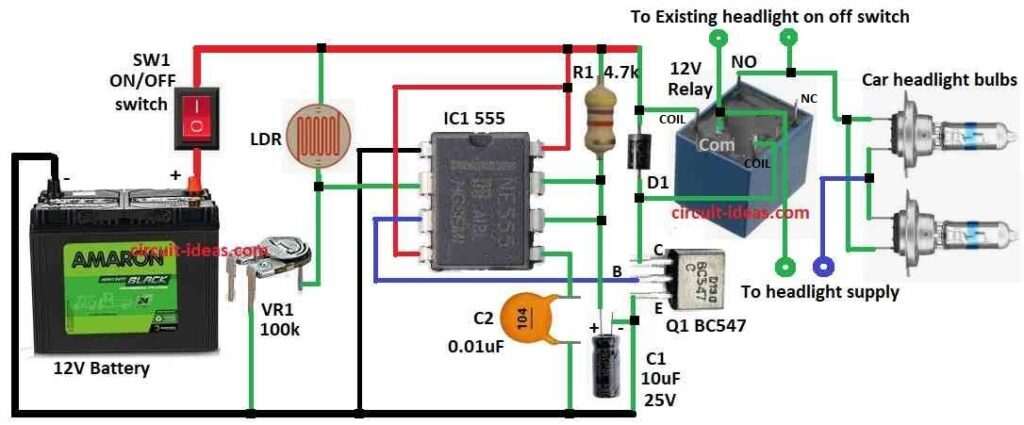
- Put all parts as shown in circuit diagram.
- Pin 1 of 555 IC connects to GND.
- Pin 2 of 555 IC connects between LDR and center leg of VR1.
- One side of LDR connects to +12V.
- Other side of LDR connects to pin 2.
- Center leg of VR1 also connects to pin 2.
- Other leg of VR1 goes to GND.
- Pin 3 of 555 IC go to base of transistor Q1 BC547.
- Pin 4 and pin 8 of 555 IC connects to +12V.
- Pin 6 and pin 7 join together.
- Add resistor R1 from +12V to this point.
- Also connect capacitor C1 here.
- Anode of C1 connects to pin 6 and pin 7 join.
- Cathode of C1 goes to GND.
Relay coil:
- One side goes to Q1 collector.
- Other side goes to +12V.
Diode D1:
- Cathode connects to +12V.
- Anode connects to Q1 collector same as relay coil.
Headlight connects between relay terminals:
- One end of headlight connects to relay common COM
- Other end connects to relay NC Normally Closed.
- Put in series with 12V supply.
SW1 switch:
- One side connects to +12V battery.
- Other side connects to +12V line in circuit.
- Battery negative goes to GND.
Conclusion:
This Smart Headlight Automation Circuit using IC 555 is smart and helpful.
It sees light around using LDR which turns ON light only when dark.
It saves power and make bulbs last long.
For driver there is no need to ON/OFF the lights for safer and easy driving.
References:
Electronic Head Lamp Glare Management System for Automobile Applications
Leave a Reply