Subwoofer Low Pass Filter Circuit using Op-Amp TL062 that let low sound go and block high sound.
This circuit is good for subwoofers which gives deep and strong bass.
The circuit uses TL062 op-amp which is active for low pass type.
It cut high sound and keep bass clean and loud.
TL062 IC from ST company has 2 J-FETs and is used for low power with fast respond.
It is good op-amp for sound and work well here.
Circuit use +12V and -12V power and help it work better.
Circuit Working:

Parts List:
| Component Type | Value | Quantity |
|---|---|---|
| Resistors (All resistors are 1/4 watt unless specified) | 220Ω | 1 |
| 39k, 4.7k, 10Ω | 2 each | |
| Potentiometer 47k | 1 | |
| Potentiometer 22k | 2 | |
| Capacitors | Ceramic 39pF, 0.47µF, 0.22µF | 1 each |
| Ceramic 0.1µF | 4 | |
| Semiconductors | IC TLC062 | 1 |
This Circuit diagram above uses op-amps and some passive parts like resistors, capacitors and power parts.
First op-amp part work as active low pass filter and second part does more filter and make signal strong.
Left and right input go through R1, R2 and then reach inverting input of op-amp which work as low pass filter.
Cutoff frequency set by VR1 and C1.
After filter the signal goes to next stage for more process.
Second op-amp part is second order low pass filter.
Final filter changes by VR2, VR3, R4, R5, C4, C5.
Output signal (filtered) go to subwoofer amp through R7.
TL062 op-amp IC uses ±12V power.
Also capacitors C2, C3, C6, C7 which are 0.1µF and resistors R3 and R6 which are 10Ω help keep power stable and circuit smooth.
Formulas with Calculations:
Below are formulas with calculations for Subwoofer Low Pass Filter using TL062 op-amp:
Cutoff Frequency (Fc):
Fc = 1 / (2 × π × R × C)
First Stage:
R = 47kΩ (47000Ω)
C = 39pF (39 × 10⁻¹² F)
Fc = 1 / (2 × 3.1416 × 47000 × 39 × 10⁻¹²)
Fc = 83.6 kHz
Second Stage:
Fc = 1 / (2 × π × √(VR2 × VR3 × C4 × C5))
VR2 = 22kΩ (22000Ω)
VR3 = 22kΩ (22000Ω)
C4 = 0.47µF (0.47 × 10⁻⁶ F)
C5 = 0.22µF (0.22 × 10⁻⁶ F)
Fc = 1 / (2 × 3.1416 × √(22000 × 22000 × 0.47 × 10⁻⁶ × 0.22 × 10⁻⁶))
Fc = 100 Hz
Circuit let sound below 100 Hz pass easily.
High sound get weak which is good for subwoofer use.
How to Build:
To build a Subwoofer Low Pass Filter Circuit using Op-Amp TL062 following steps should be followed while designing ourr own circuit:
- Pin 1 of IC1 go to one side of VR1 and other side of VR1 go to pin 2 of IC1
- Resistor R2 from left audio input go to pin 2 of IC1
- Capacitor C1 connect parallel with VR1
- Resistor R1 from pin 2 of IC1go to right audio input
- Pin 3 of IC1 go to GND
- Pin 4 of IC1 go to -12V through R6 and also connect C6 and C7 which is parallel from this point to GND
- Center pin of VR2 and VR3 go to one side of C4 and other side of C4 go to pin 6 of IC1
- Resistor R5 one side go to VR3 and other side go to C5 and then to GND
- Pin 5 of IC1 connect at point between R5 and C5
- Resistor R4 go to pin 1 of IC1 and other end of R1 go to VR2 pin
- Pin 7 of IC1 connect to pin 6
- Pin 7 also go to audio output through R7
- Pin 8 of IC1 go to +12V through R3 and connect C2 and C3 parallel from here to GND
12V Dual Power Supply for the above Circuit:
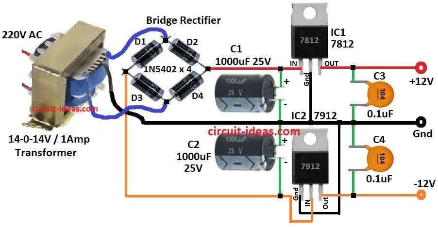
Working of 12V dual power supply circuit:
220V AC step down to 14-0-14V AC using center tap transformer with 1A rating.
Center tap is GND (ground).
Bridge rectifier is made with 4 × 1N5402 diodes.
D1 + D3 work in positive half and D2 + D4 work in negative half.
Converts AC to pulsing DC.
Two 1000µF 25V capacitors C1, C2 are used to smooth DC and reduce ripple.
Output becomes approx with +19V and -19V DC before regulation.
7812 IC1 regulate +19V DC to +12V DC and 7912 IC2 regulate -19V DC to -12V DC.
C3, C4 are 0.1µF capacitors help remove high frequency noise and keep voltage clean.
Final result shows: IC1 7812 gives +12V DC, IC2 7912 gives -12V DC and GND is center tap
It is good dual supply for op-amps, audio amps and circuits which need ±12V DC.
Conclusion:
This Subwoofer Low Pass Filter Circuit using Op-Amp TL062 is a good and useful project.
It remove high sounds and boost bass.
It use TL062 op-amp and make sound clear and stable.
We can change cutoff by adjusting resistor and capacitor which fit many audio setups.