
Sometimes we need to make a quick decision but choosing is not easy, so we flip a coin; now imagine doing the same with electronics.
This transistor-based coin toss game circuit works like a real coin toss and produces a random result every time, and when we apply power to the circuit, no one can predict the outcome.
One LED will glow randomly and so the decision is fair; moreover, the circuit is very simple and also it is good for beginners and therefore, this project is fun and useful.
Circuit Working:
Parts List:
| Components | Values | Quantity |
|---|---|---|
| Resistors | 470Ω | 2 |
| 1k, 10k, 3.3k | 2 each | |
| Capacitors | Electrolytic 10uF 25V | 2 |
| Electrolytic 220uF 25V | 1 | |
| Semiconductors | Transistors BC547 | 2 |
| Open Push Button Switch | 1 | |
| LEDs any color | 2 | |
| Power Supply 9V DC | 1 |
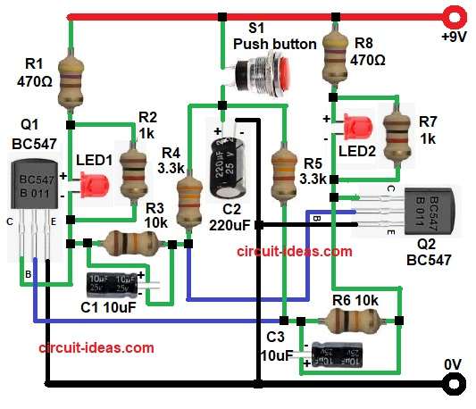
This circuit works as an astable multivibrator and it uses two NPN transistors in cross-coupled connection, in astable multivibrator, no state is stable and both transistors switch ON and OFF again and again; therefore, this action depends on resistors and capacitors.
First, the 9V power supply powers the circuit and when we press push button S1, capacitor C2 delivers a short power pulse while capacitors C1 and C3 start charging simultaneously.
Now both transistors try to turn ON, but due to small component difference one transistor turns ON first, so balance breaks and one transistor goes ON and other goes OFF.
If Q1 turns ON then LED1 glows and if Q2 turns ON then LED2 glows and after switch release the oscillation stops and only one LED stays ON.
So output looks random and hence, circuit works like electronic coin toss.
Formula with Calculation:
Below is Astable multivibrator time period formula:
T = 0.693 × (R × C)
here,
- R is 10k
- C is 10uF
So,
T = 0.693 × 10000 × 10 × 10^-6
T = 0.0693 seconds
Frequency formula:
F = 1 / T
F = 1 / 0.0693
= 14.4 Hz
Hence, this fast switching creates randomness.
How to Build:
To build a Transistor Based Coin Toss Game Circuit follow the below connection steps:
- First, gather all the parts as shown in circuit diagram.
- Next, Q1 transistor emitter pin goes to ground, collector pin goes to LED1 and resistor R1, R2 and R3 and base pin connects to resistor R3, R5, R6 and capacitor C3
- Then Q2 transistor emitter pin goes to ground, collector pin goes to LED2 and resistor R8 and base pin connects to resistor R4 and capacitor C1.
- Now resistor R2 connect parallel to LED1 and resistor R7 connect parallel to LED2
- Further, capacitor C2 positive connects switch one end and negative connects to GND.
- Finally, power supply 9V positive goes to VCC line and 9V negative goes to ground.
Conclusion:
To conclude, this Transistor Based Coin Toss Game Circuit is simple and fun to try for, it uses basic electronic components and it works on a simple concept.
Transistor mismatch produces randomness, so the circuit cannot predict the results, hence, this behavior makes the circuit ideal for beginners because it helps them understand multivibrators more clearly, making it an excellent learning project.