Stepper motors are good for robots, CNC, automation and to move very exact.
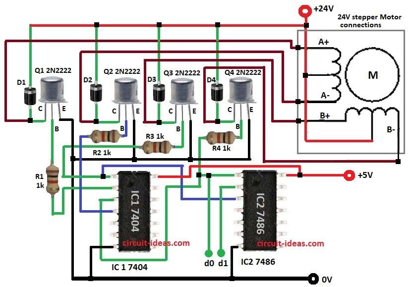
Transistor Based Stepper Motor Drive Circuit run unipolar motor with logic gates and transistors and it use four 2N2222 to control motor windings, two NOT gates, one XOR gate and to read 2-bit control to turn ON 4 windings.
Also, circuit needs parts like IC 7404, IC 7486, transistors, diodes with these all make correct pulse order for motor.
Logic ICs use 5V and motor use 24V DC.
Circuit Working:
Parts List:
| Components | Values | Quantity |
|---|---|---|
| Resistors | 1k 1/4 watts | 4 |
| Semiconductors | ICs 7404 | 1 |
| 7486 | 1 | |
| Transistors 2N2222 | 4 | |
| Diodes 1N4007 | 4 | |
| 24V stepper motor | 1 |
Motor works by turning coils in set order; four steps like A+, A-, B+, B- make motor spin and d0, d1 signals choose pulse order.
IC1 7404 NOT flips signals and IC2 7486 XOR makes step pattern, Q1 to Q4 2N2222 transistors are switches for coil current and D1 to D4 1N4007 diodes stop back EMF and R1 to R4 resistors 1kΩ limit current.
Furthermore, change d0, d1 and IC1 and IC2 which give right pulses through which motor turns smooth and exact.
How to Build:
To build a Transistor Based Stepper Motor Drive Circuit follow below steps for connection:
- First, get all parts as per circuit diagram
- Then connect pin 1 of IC1 7404 to base of Q3 through R3.
- Next, connect pin 2 of IC1 to base of Q1 through R1.
- Now connect pin 3 of IC1 to base of Q4 through R4.
- After that, connect pin 3 of IC1 to pin 1 of IC2 7486.
- Also, connect pin 4 of IC1 to base of Q2 through R2.
- Further, connect pin 1 of IC1 to pin 3 of IC2 and connect pin 1 of IC2 to control d0.
- Then connect pin 2 of IC2 to control d1.
- Connect pin 7 of IC1 and IC2 to GND and then connect pin 14 of IC1 and IC2 to +5V.
- Now connect all emitters of Q1 to Q4 to GND and connect anode of D1 to D4 from collectors of Q1 to Q4 and cathodes to +24V.
- Finally, connect collector of Q1 to A+ of motor, connect collector of Q2 to A- of motor, connect collector of Q3 to B+ of motor and connect collector of Q4 to B- of motor.
Conclusion:
Overall, this Transistor Based Stepper Motor Drive Circuit is easy with transistors and logic driver for unipolar stepper, as this circuit is also, good for beginners.
So if required, change logic sequence for other stepper designs.
Leave a Reply