A power supply plays an important role in electronics because every circuit requires a proper DC voltage, but however, a fixed voltage is not always sufficient, so many applications require an adjustable voltage supply.
This 0–20V regulated power supply circuit using transistors is simple, low-cost, and uses readily available components, also beginners can build it easily, and they can use it for laboratory testing and hobby projects.
Furthermore, this circuit converts AC to DC first, then it filters and regulates voltage and after that it provides smooth adjustable output from 0 to 20 volts.
Circuit Working:
Parts List:
| Components | Values | Quantity |
|---|---|---|
| Resistors | 1k 2 watt, 1k 1/4 watt, 1k 1 watt, 3.3k 1/4 watt | 1 each |
| Potentiometer 5k | 1 | |
| Capacitors | Electrolytic 1000uF 35V, 100uF 35V | 1 each |
| Ceramic 0.1uF | 2 | |
| Semiconductors | Transistors BC547, TIP41 | 1 each |
| Zener Diode 10V 0.5 watt | 2 | |
| Bridge Diode 1N4001 | 4 | |
| Diode 1N4001 | 1 | |
| Transformer secondary 0V-18V AC, primary AC 220V or 120V | 1 | |
| Fuse 0.5A | 1 | |
| On-Off switch | 1 | |
| Heat sink for TIP41 | 1 |
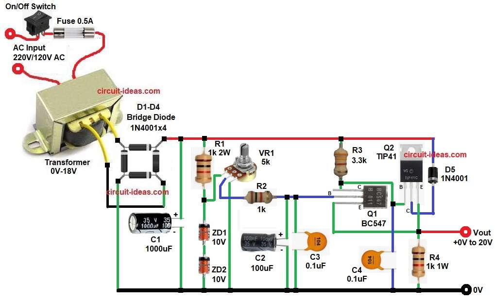
At first, AC input 220V or 120V given to transformer.
ON- Off switch controls power and fuse gives protection, then this transformer steps down voltage to 18V AC, so high voltage becomes safe low voltage.
Next, 18V AC goes to bridge rectifier, with diodes D1 to D4 convert AC into pulsating DC and however, this DC still contains ripples, therefore, capacitor C1 1000uF used, as it filters pulsating DC and makes smoother DC.
After filtering the DC voltage is around 24V DC approximately, and now regulation section starts working; then R1, ZD1 and ZD2 form reference voltage circuit, two 10V Zener diodes create stable reference voltage around 20V, because each Zener is 10V, so total is 20V.
Variable resistor VR1 connected to adjust voltage level and when we rotate VR1 the voltage at base of BC547 changes and consequently output voltage changes.
Then BC547 Q1 works as driver transistor and it controls base current of Q2 TIP41 transistor.
TIP41 is main pass transistor and it handles load current, as base voltage changes the emitter voltage also changes, and thus output voltage becomes adjustable.
Capacitors C2 and C3 reduce noise and also C4 improves stability at output and diode D5 protects transistor from reverse voltage.
Finally, output voltage taken from emitter of TIP41 and output can vary from 0V to nearly 20V.
How to Build:
To build a 0-20V Regulated Power Supply Circuit using Transistors follow the below connection steps:
- Start, the circuit by collecting all the circuit parts as shown in circuit diagram above.
- Then start with transformer primary pins connect to AC mains 220V or 120V and secondary two wires connect to bridge rectifier AC input.
- After that, connect the transformer output to the two AC input terminals of the bridge rectifier.
- Connect the positive output of the bridge rectifier to the positive terminal of capacitor C1, and connect the negative output to the ground line.
- Now C1 1000uF positive pin goes to rectifier positive and negative pin go to ground.
- Zener Diodes ZD1 and ZD2 connect in series, with cathode of first to R1 and anode of second to ground.
- Also, R1 resistor one side goes to filtered DC positive and other side goes to ZD1 cathode.
- Further, VR1 one end go to reference voltage and other end go to ground, middle pin go to R2 and base of Q1.
- Next, Q1 BC547 transistor collector pin goes to R3, base go to R2 from VR1 and emitter goes to junction of emitter of Q2, Vout
- Resistor R4 one end and other end of R4 goes to ground.
- Similarly TIP41 Q2 collector pin goes to cathode of D5 anode of D5 goes to AC input, base goes to BC547 collector and emitter goes to junction of Vout emitter of Q1 and one end of resistor R4.
- Then C2 100uF positive go to base control line and negative to ground
- C3 0.1uF goes between base and ground for noise filter.
- Finally, C4 0.1uF one end goes between collector of Q1 and base of Q2 transistor and other end to ground.
Conclusion:
To conclude, this 0-20V Regulated Power Supply Circuit using Transistors is a simple and useful project because it provides adjustable DC voltage for testing circuits and it also uses low-cost, readily available components.
Working is easy to understand and however, proper heat sink is necessary for high current; also transformer rating must be correct and if constructed carefully then it gives stable and reliable output.
Therefore, it is very good project for students and hobby electronics users.

Leave a Reply