If we have 1.5V AA battery but gadget need 10V to work.
Then this 1.5V To 10V Boost Converter Circuit is small power maker.
It changes 1.5V weak power to strong 10V.
This circuit is useful for devices which need more power than what battery gives.
Circuit Working:
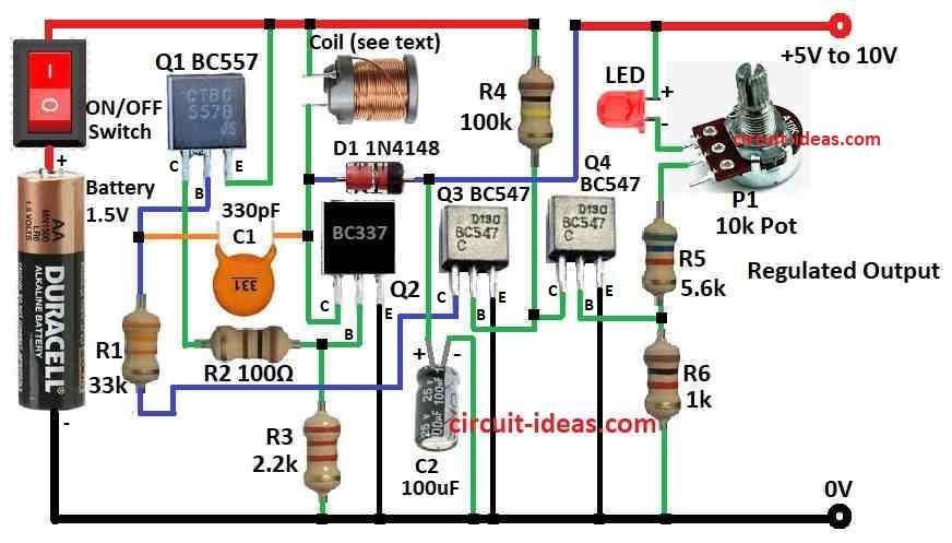
Parts List:
| Category | Component | Quantity |
|---|---|---|
| Resistors (All resistors are 1/4 watt unless specified) | 33k | 1 |
| 100Ω | 1 | |
| 2.2k | 1 | |
| 100k | 1 | |
| 5.6k | 1 | |
| 1k | 1 | |
| Potentiometer 10k | 1 | |
| Capacitors | Ceramic 330pF | 1 |
| Electrolytic 100µF 25V | 1 | |
| Semiconductors | Transistors BC547 | 2 |
| Transistors BC557 | 1 | |
| Transistors BC337 | 1 | |
| Coil 70 turns 0.25mm on 10mH choke | 1 | |
| Diode 1N4148 | 1 | |
| LED 5mm, 20mA | 1 | |
| ON/OFF switch | 1 | |
| Battery 1.5V-4.5V | 1 |
This smart circuit changes 1.5V to 10V saving cost instead of using expensive 9V batteries.
It also gives 5V for microcontroller use.
Main feature is it saves power and uses less than 8mA when there is no load connected.
With 470Ω load at 10V it gives 20mA current and voltage drop is very small under 10mV.
We can adjust output voltage from 5.3V to 10V using potentiometer.
How it works:
100k resistor turns ON BC547.
BC547 turns ON BC557 through 33k resistor.
BC557 switches ON BC337 through 100Ω resistor.
As more current flows resistor value lowers allowing more current.
BC337 pulls current through inductor and builds magnetic field (flux) and blocks extra current at first.
As collector voltage drops the 330pF capacitor helps BC557 turn ON more.
This continues until BC337 is fully ON and then capacitor starts turning BC557 OFF which also turns BC337 OFF.
When both are OFF inductor flux collapses creating high voltage spike which can go 100V+ but with low current.
This spike charges 100uF capacitor up to 10V.
Third transistor then controls output to stay stable at 10V.
Formulas and Calculations:
When making a boost converter we need to choose parts based on what we need like current, efficiency, input/output voltage etc.
Here is a simple design guide for a 1.5V to 10V boost converter:
1. Duty Cycle (D):
Use this formula:
D = Vout / (Vin + Vout)
For this circuit:
D = 10V / (1.5V + 10V) = 0.8696
So duty cycle is about 87%.
2. Inductor Value L:
Use this formula:
L ≥ (Vin − Vout) × Vout / (f × ΔI)
where:
- Vin is 1.5V
- Vout is 10V
- f is the switching frequency
- ΔI is the ripple current which is usually 10 to 30% of average output current
Important Notes:
Choose components carefully for stable and efficient boost.
Real values may change based on exact needs and parts used.
Test and adjust to get the performance we want.
How to Build:
To build a 1.5V To 10V Boost Converter Circuit we need to follow the below mentioned steps for connections:
Connect Transistors:
- Q3 BC547 emitter goes to ground.
- Q3 base connect to 100k resistor and other side to 1.5V battery (+).
- Q3 collector goes to Q1 BC557 base.
- Q1 emitter goes to positive supply.
- Q1 base also connect to 33k resistor and other side back to Q3 collector.
Connect Q2 BC337:
- Q1 collector connect to 100Ω resistor and then to Q2 base.
- Q2 emitter goes to ground.
- Q2 collector goes to one side of inductor.
Voltage Regulation Part:
- Other side of inductor connect to diode anode.
- Diode cathode goes to 100μF capacitor.
- Other side of capacitor goes to battery positive (+).
Potentiometer and Output:
- 10k pot connect to output.
- One side of pot goes to positive supply.
- Other side goes to LED.
Final Touches:
- All grounds connect together.
- Connect 330pF capacitor between Q1 BC557 collector and Q2 BC337 collector.
- Power circuit with 1.5V.
- Adjust pot to get output between 5.3V and 10V.
Important:
Check all wires and parts before turning ON.
- Be careful with high voltage which can be dangerous.
- We may need to modify values depending on actual parts.
Conclusion:
This 1.5V To 10V Boost Converter Circuit using simple parts like transistor, inductor, diode and capacitor.
It is very useful for devices which need higher voltage from small battery.
References:
How does this 4-transistor DC-DC 1.5V to 9V boost converter work?
Leave a Reply