12V Battery Level Indicator Circuit using IC LM3914 show how much battery power is left.
It is good for devices using 12V battery and help avoid sudden power OFF.
IC LM3914 senses voltage and control 10 LEDs.
It show in dot mode or bar mode.
It work with 3V to 25V power supply.
LEDs light up one by one as voltage increase.
This circuit is useful for 12V lead-acid battery and for similar use.
Circuit Working:
Parts List:
| Component | Specification | Quantity |
|---|---|---|
| Resistors | 56k 1/4 Watt | 1 |
| 18k 1/4 Watt | 1 | |
| 4.7k 1/4 Watt | 1 | |
| Preset 10k | 1 | |
| Semiconductors | IC LM3914 | 1 |
| On/Off Switch for dot or bar mode | 1 | |
| LEDs Any 5mm 20mA | 10 |
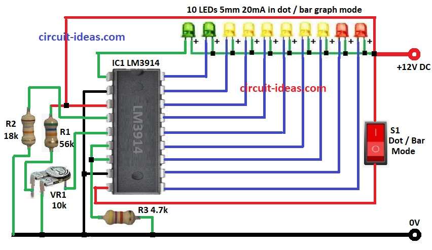
LM3914 chip show voltage level by turning ON 10 LEDs.
It work in two ways: DOT mode with only one LED ON or BAR mode with many LEDs ON up to certain voltage.
Pin 9 controls the mode.
Press switch S1 and pin 9 get positive voltage with BAR mode ON.
No press then pin 9 is not connected and DOT mode is ON.
Resistors R1, VR1, R3 make voltage divider to give right input to LM3914.
Pin 7 of LM3914 give reference voltage for LED levels.
When battery voltage changes then LEDs light up to show level clearly.
Formulas:
Formulas for 12V Battery Indicator using LM3914:
1. Input Voltage Scaling:
Battery voltage must go lower to match LM3914 range.
V_scaled = V_input × VR1 / (R1 + VR1 + R3)
where,
- V_scaled is the voltage going to LM3914
- V_input is the battery voltage for 12V
- R1, VR1, R3 are the resistors used to scale down
2. LED Thresholds:
Each LED turns ON at part of reference voltage.
V_LEDn = n × V_REF / 10
where,
- V_REF is the voltage from pin 7 to about 1.25V to 5V
- n is the LED number from 1 to 10
- 10 is the total LEDs in the circuit
LEDs light one by one as voltage goes up.
How to Build:
To build a 12V Battery Level Indicator Circuit using IC LM3914 follow the below mentioned connections steps to design our own circuit:
- Gather all parts as shown in circuit.
- Pin 1 of IC1 connects cathode of LED1 and anode of LED1 connects to +12V.
- Pin 2 of IC1 connects to GND.
- Pin 3 of IC1 connects to +12V supply.
- Also connect Pin 3 to one side of R1.
- Other side of R1 goes to upper leg of VR1.
- Center leg of VR1 connects to pin 5.
- Third leg of VR1 goes to GND.
- Pin 4 connects to GND through resistor R3.
- Pins 6 and 7 are joined together and are connects to GND through resistor R4.
- Pin 8 connects to GND.
- Switch S1 connects between pin 9 and +12V for mode select.
- Pin 10 connects to cathode of LED10 and anode of +12V.
- Pin 11 connects to cathode of LED9 and anode of +12V.
- Pin 12 goes to cathode of LED8 and anode goes to +12V.
- Pin 13 connects to cathode of LED7 and anode goes to +12V.
- Pin 14 connect to cathode of LED6 and anode connects to +12V.
- Pin 15 goes to cathode of LED5 and anode goes to +12V.
- Pin 16 goes to cathode of LED4 and anode goes to +12V.
- Pin 17 goes to cathode of LED3 and anode goes to +12V.
- Pin 18 goes to cathode of LED2 and anode goes to +12V.
Conclusion:
This 12V Battery Level Indicator Circuit using IC LM3914 is easy and useful project.
LEDs show battery power clearly.
It is simple to build with not many parts needed.
If understand how it works and by using proper formulas from above we can change it for other voltages too.
Leave a Reply