12V SMPS driver change big AC power from 110V or 220V into small 12V DC, also circuit is good for LED strip light.
Furthermore, in this DIY project we can make cheap and strong LED driver, which can power full 12V LED strip with 100 or 200 LEDs.
Important points to follow:
Here, Circuit uses 230V AC direct which is very dangerous and only safety is at short-circuit protection at output.
Therefore, if we want to make SMPS then first learn well and follow trusted diagram and take safety care and only try if having good skill and knowledge in electronics.
Circuit Working:
Parts List:
| Components | Values | Quantity |
|---|---|---|
| Resistors (All resistors are 1/4 watt unless specified) | 4.7M | 2 |
| 22Ω | 1 | |
| 220Ω | 1 | |
| 1k | 1 | |
| 43k | 1 | |
| 12k | 1 | |
| Capacitors | Ceramic 470pF 200V | 1 |
| Ceramic 100nF 50V | 1 | |
| Electrolytic 22μF 400V | 1 | |
| Electrolytic 10μF 50V | 1 | |
| Electrolytic 470μF 25V | 1 | |
| Semiconductors | IC TNY285DG | 1 |
| IC PC817 | 1 | |
| IC TL431 | 1 | |
| SMBJ160A TVS diode | 1 | |
| UF4007 diode | 1 | |
| SB380 schottky diode | 1 | |
| Bridge Rectifier MB10S | 1 | |
| Transformer Ferrite core (see specific requirements) | 1 |
To begin with, first learn how LED strip driver work and its parts, as the circuit is high voltage so we need to keep in strong box for safety.
For learning we have made a simple test on veroboard with no solder.
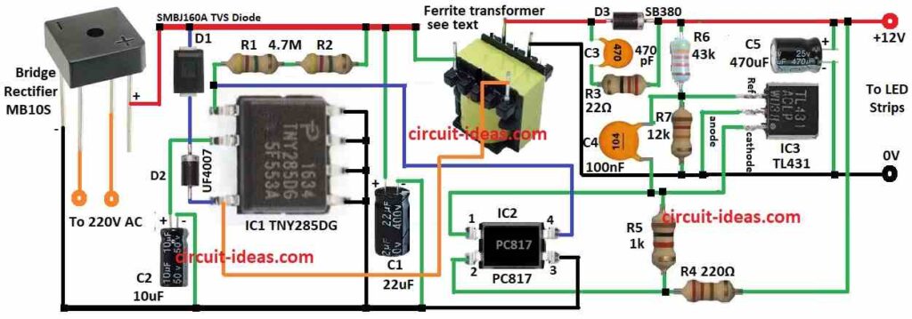
Moreover, C1 feedback capacitor control output voltage and TNY285DG main IC drives transformer and switch 125 kHz.
Then C2 supply capacitor keeps IC smooth and R1, R2 are under voltage lockout and they stop IC if input low.
After that, D1, D2 protect IC from spikes and D3 Schottky SB380 rectify and control current and snubber R3 and C3 protect D3.
Also, C5 output capacitor keeps LED power steady and PC817 optocoupler isolate high voltage from low to do feedback.
Transformer Construction:
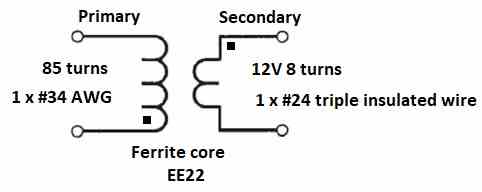
Steps to Make Transformer:
First, start winding 85 turns from pin 2 and use 34 AWG single wire with double coated.
Then wind clockwise left to right and second layer wind right to left.
Next layer clockwise again.
Last layer spread wire evenly and finish at pin 1 and use 3 layers polyester tape 1 mil and 8.45 mm wide.
After that, start pin 7 and wind 8 turns 24 AWG triple insulated single wire clockwise and spread evenly and finish at pin 6.
Now add 2 layers tape over windings and then put core halves together tight.
Do not use a vacuum dip; instead, apply the varnish evenly.
Formulas:
Important Formulas for Designing 12V SMPS Driver for LED Strip with ICs:
1. Turns Ratio (Np/Ns):
Np/Ns = √[Vout∗(Vin−Vout)]/[Vin∗f∗Ae]
where,
- Np is in primary turns
- Ns is in secondary turns
- Vin is the input voltage for 12V
- Vout is the output voltage for 12V
- f is the frequency in kHz
- Ae is the cores effective area
2. Peak Primary Current (Ipeak):
Ipeak = Vin∗Dmax/(f∗Ae)
Dmax = Max duty cycle
Use this to find highest current in primary winding.
3. Output Capacitor (Cout):
Cout≥Iout∗(1−D)/(f∗ΔVout)
where,
- Iout is the output current
- D is the duty cycle
- ΔVout is the ripple voltage at output
Hence, this helps to choose the right capacitor.
4. Feedback Voltage Divider:
Vout / Vref = Rtop / Rbottom
where,
- Vref = The TL431s reference voltage, which is usually 2.5V.
5. Efficiency (η):
η = Pout / Pin × 100%
where,
- Pout is the output power
- Pin is the input power
How to Build:
To build a 12V SMPS Driver Circuit for LED Strip follow the below mentioned steps for connections:
- First, gather all parts as shown in circuit diagram.
- Next, pin 1 connect to (+) supply through R1 and R2
- Then pin 2 connect to GND through C2
- Now pin 4 connect to (+) supply through D1 and D2
- After that, pins 5, 6, 7, 8 connect all to GN and connect from (+) supply to GND
- Then IC2 pin 1 connects to cathode of IC3
- Next, IC2 pin 2 connects to (+) supply and IC2 pin 3 connects to GND
- Also, IC2 pin 4 connects to pin 1 of IC and IC3 pin 1 connects to capacitor C4
- After that, anode of IC3 connects to 0V GND and cathode of IC3 connects to pin 1 of IC2
- Now transformer Leg 1 of primary side connects to 230V AC live, Leg 2 connects to pin 4 of IC1, Leg 3 connects to GND 0V, Leg 4 go to secondary side of 12V DC, transformer negative leg connects to GND and transformer positive leg connects to 230V AC live
- Finally, other 2 legs connects to AC power input L and N.
Conclusion:
To conclude, making 12V SMPS Driver Circuit for LED Strip is good and useful project, as it works better than linear regulators and saves more power and makes less heat; but be careful with high voltage is dangerous.
Also, always unplug before touching any parts, work in good light and ask expert if unsure about electronics.
Therefore, start always with small low voltage projects first.