
This article is for 50Hz Square Wave Generator Circuit using Transistors, here, two transistors switch ON and OFF one by one and outputs blink opposite time.
We used no ICs; we require only simple components, and this circuit also helps us understand the basic working of an oscillator.
Also, we can change the resistor or capacitor values to adjust the speed.
Circuit Working:
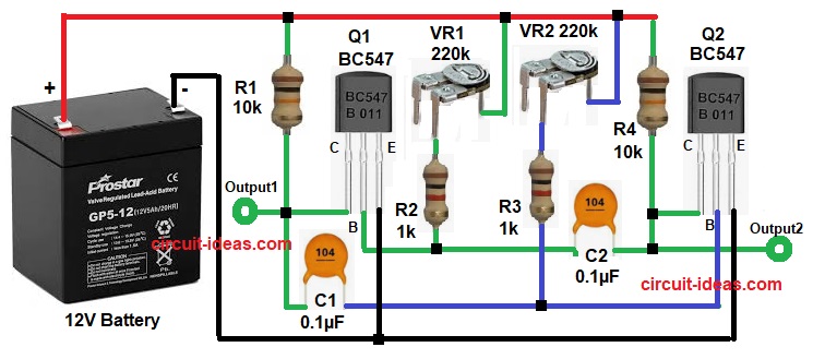
Parts List:
| Components | Values | Quantity |
|---|---|---|
| Resistors | 10k 1/4 watt | 2 |
| 1k 1/4 watt | 2 | |
| Preset 220k | 2 | |
| Capacitors | Ceramic 0.1µF | 2 |
| Semiconductors | NPN Transistor BC547 | 2 |
| Battery / Power Supply 12V DC | 1 |
When power supply is ON the circuit start by itself and due to small difference, one transistor turn ON first, then its output become active and other transistor stays OFF.
After that, capacitor connected to ON transistor start charging and after some time the capacitor discharge to other transistor base; this make second transistor ON and first transistor OFF.
Now second capacitor start charging and after delay, it discharge back and turn first transistor ON again and this switching continue again and again.
Hence, because of this, square wave output generate and both outputs work opposite time.
How to Build:
To build a 50Hz Square Wave Generator Circuit using Transistors follow the below connection steps:
- First, assemble all parts as per circuit diagram.
- Next, emitter pin of Q1 and Q2 both connect to ground, collector of Q1 connects with R1 and C1 and collector of Q2 connects with R4 and C2.
- Then base of Q1 connects with C2 and VR1 through resistor R2 and also base of Q2 connects with C1 and VR2 through resistor R3.
- Now R1 and R4 connect from +12V to collectors and VR1 and VR2 connect from +12V to transistor bases.
Conclusion:
Overall, this simple and low cost 50Hz Square Wave Generator Circuit using Transistors uses only basic parts and circuit is easy to make and understand.
Furthermore, output frequency depends on resistor and capacitor and by changing RC value, different frequency we can get.